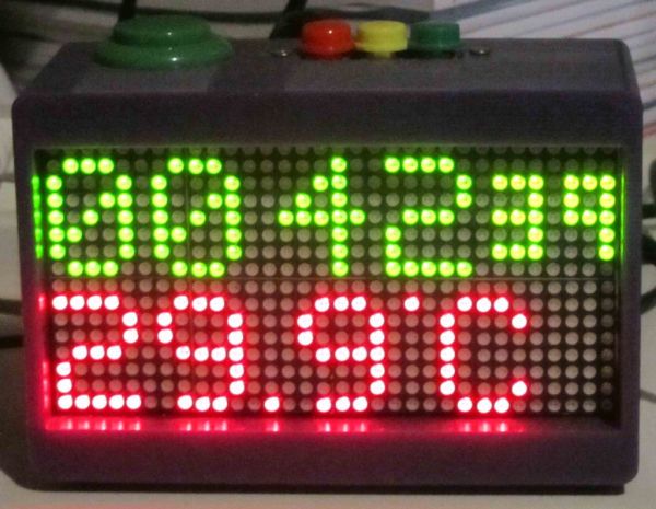
This is a funny looking clock that has that displays time on relatively large 32×16 Bi-Color LED Matrix.
It includes also a countdown counter that I find very useful in many situations.
Features:
- Date And time display
- Temperature display
- Countdown timer
- Buzzer notification
- Randomly changing colors of display
- Display intensity control (brightness)
Aside the fact it is fun to build, you might ask why do that?
Well, I have few good uses for it, one of them is ensure in meetings people are respectful of time and are not taking all the time for their own topics. Good for ship-room or SCRUM meetings.
Step 1: Parts
Following is a list of parts and for the “special” ones a link for where you can buy them. Consider searching eBay or other stores for getting best prices.
1x Arduino board (Mini/Nano or other)
1x HT1632 LED Dot Matrix display http://store.arduino.cc/ww/index.php?main_page=product_info&cPath=6&products_id=178
1x DS1820 Temperature Sensor (The DS18B20 is good as well).
1x DS1340 Real-Time clock (RTC) module http://www.gravitech.us/i2crecl.html
3x Push Buttons http://www.gravitech.us/mopubusw12sq.html
1x Arcade push button http://www.gravitech.us/pubu33bl.html
5x 4.7K Resistor
1x 10uF Capacitor
1x 5V Buzzer http://www.gravitech.us/acbuzzer4v8v.html (I actually bought a different one in local store for much cheaper price)
You might also need some male-to-female jumper wires like these: http://www.ebay.com/itm/30pcs-1pin-Wire-Male-Female-Jumper-Cables-for-Shield-or-EQUIV-/190720063441?pt=LH_DefaultDomain_0&hash=item2c67cd37d1 to connect between the display and the Arduino. Also, depending on the exact format of the RTC module, you might need different jumper wires too. If you go with the one mentioned above, it has male header so you can use these male-to-female wires. For connecting the display you need 6 wires and for the RTC 4 wires. Depending on how and what type of buttons you choose, you will need wires and optionally a bread-board to place them on.
Notes:
a) The LED Matrix is pretty nice one and comes from Sure Electronics. Apparently there is a confusing list of variants for this type of display. The link to the Arduino store is where I got mine.
b) You can easily change the RTC to be any other, including DS1307 based which is cheaper (less than $4.00 on eBay). Minor code modifications might be required depending on which RTC module you choose.
c) I used Arduino Nano that also has the USB connection, easier to program it and all. To save on cost you can choose any variant actually that is 5V one (the matrix display is designed for 5V logic)
d) The current drawn by the LED matrix is relatively high so make sure to provide thick wires for ground and Vcc
Step 2: Operating the clock
Basically there are three modes the clock works in:
Modes of operation
1. Standard mode, displaying time and flipping 2nd line between date and temperature
2. Setup mode, where the user can adjust time and date
3. Countdown mode: First line display current time and 2nd line showing the time remaining for countdown
In Standard Mode
Pressing “Plus” or “Minus” buttons increases and decreases the display intensity respectively.
Pressing “Setup” moves the clock to Setup mode.
Pressing “Start/Stop” moves the clock to Countdown mode
The 2nd line will display the following information, flipping from one to the other every 2 seconds.
Day-of-week + Day-in-month
Month-Name + Year (last 2 digits)
Day-in-month + Month Number + Year (4 digits)
Temperature
Also, in this mode the color used to display this information is changing every 4 seconds and is different for first and seconds line.
In Setup Mode
With each press of Setup the focus of time and date part changes and displayed in Red.
The “Plus” and “Minus” buttons changes the value
Pushing “Setup” gets you to edit Hour, Minute, Seconds, Day in month, Month and Year
After you completed setting up the time and date additional push on “Setup” will get you back to “Standard” mode.
In Countdown Mode
Once you enter to this mode, the time to countdown is displayed on the 2nd line with a Yellow down arrow. Pushing “Setup” lets you edit the time to countdown. “Plus” or “Minus” buttons will be used to set minutes and seconds.
Pushing “Start/Stop” again in this mode will start the countdown, time left will be displayed on the 2nd line with a Red down arrow. Once countdown is complete a buzz will be heard and the clock will return to start of countdown mode.
During countdown, the color of the time left changes from Green while time is more than a minute, Yellow when 59 seconds or less are remaining and eventually turn Red in the last 10 seconds (see pictures of this step).
During countdown, pressing “Start/Stop” again will stop counting down and restore countdown time to the previously set time like when you just entered the countdown mode.
The countdown period you set is preserved between operations and between power recycles (stored on Arduino EEPROM)
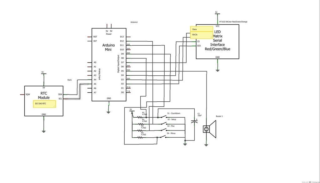
Step 3: Schematic and Assembly
Assembling this instructable is pretty straight forward for people who experienced building any electronics/Arduino projects. If you need any assistance in programming Arduino, please search in this site for more details on how to download the IDE and how to program an Arduino board.
Connecting the components can be done pretty easily using of the shelf connector cables like these one, or you can practice your ironing for more firm assembly.
Please take a look at the drawing here. As the drawing tool does not have in its library all the components I used here, so I draw using the closest ones available with yellow notes on setting the right connections.
The circuit for the DS1820 is shown separately. Make sure to place the sensor as far as you can from the display as the display itself does dissipate some heat that will influence the temperature reading.
I included a mechanical diagram for the case I built with a 3D printer I got lucky to get some access to thanks to a good friend who works in one of the firms that produces those incredible machines.
Connect the components according to the diagram and upload the code into your Arduino using its IDE (Arduino IDE 1.0 or 1.0.1).
Setup the time and date and you are all set.
Buzzer notification