Summary of Arduino Nano based Microbot
This instructable shows how to build a palm-sized Arduino Nano micro-robot using two modified 9 g servos with Tamiya tracks, a custom battery pack, a 40-pin DIP socket, an eraser as a chassis spacer, and simple wiring. Steps cover converting servos for continuous rotation, fitting and drilling track hubs, making a small NiCd battery pack, wiring the Nano via a socket with jumper power switching and charging access, assembling with zip ties, and programming in the Arduino environment.
Parts used in the Microbot:
- Arduino Nano
- Small rechargeable battery (example: 4-cell NiCd pack ~4.8 V)
- Pair of 9 g micro servos, modified for continuous rotation
- Tamiya track set (drive and idler hubs and tracks)
- 40 pin DIP socket
- Rubber eraser (frame spacer/suspension)
- Zip ties
- Resistors for servo potentiometers (around 5k, 1k–10k acceptable)
- Screws for mounting hubs (Tamiya kit screws or servo screws)
- Electrical tape
- Wire and jumper pieces
This instructable was created to be entered in the Robot Challenge. If I win, the parts will of course, go into robots like this one. Notes on how to include some of the very components in the prize packages are given in the last step. I am 28, so of course, I’m not going for the student prizes.
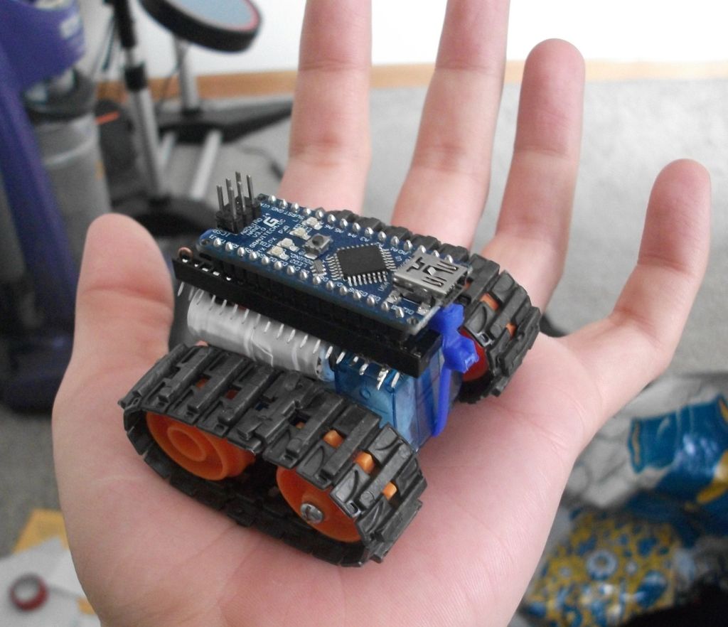
I created this as a simple project for those just starting out in robotics. It is relatively inexpensive, requires minimal tools and is easy to build. Once finished you have an expandable robotic platform that fits in the palm of your hand and can be easily programmed in the Arduino environment.
Here is is driving in a triangle, without any special add ons
In the instructions I’ll walk you through how to:
- Modify the servos for continuous rotation
- Fit the track hubs on to the servos
- Make a custom battery pack
- Wire it with a few connections
- Assemble it
- Program it
- Customize
These and other additions can be mixed to make your own custom micro robot
For the basic platform the following supplies are needed:
an Arduino nano
a small rechargeable battery
a pair of 9 g servos, modified for continuous rotation
part of a Tamiya track set
a 40 pin dip socket
a rubber eraser
some zip ties
Step 1: Construction: Modify the servos
Micro servos modified for continuous rotation are the heart of this design. They give you so much of the hardware; the motors, the gearbox, the driver and control circuitry, all in a tiny cheap package, and in this implementation they also act as the frame of the robot (seen in the next step). There are many instructables on modifying servos for continuous rotation. But here is how I did it for the micro 9g servos I am using.
Pictures:
- Remove the tiny screws and open the case
- Cut the potentiometer wires, these are where you will attach the resistors
- If you have surface mount resistors, place a 5k (1k to 10k should work) on the pad from each of the side pads to the middle pad, if you don’t twist a pair of through hole resistors like this
- Break out the stop on the potentiometer with some small pliers, you need the pot for its use as a rotational bearing
- solder on the resistors, if you used the pair of through hole ones, I recommend bundling them in electrical tape like so. For the servo that will go on the front, cut a notch for the wire to exit through the side so it doesn’t come from under the robot.
- (not shown) Before you close up, put a hole in the back part of the case opposite the spline to mount the idler (wheel with no teeth).
- Use some angle cutters or pliers to remove any mounting flanges from the cases and file or sand down the ridges they leave, these can get in the way later.
Step 2: Construction: Drill the hubs to size
- Cut the stems on the hubs so that they just stick past the inner edge of the tracks when installed. This can be done with a hobby knife saw or a coping saw. Be careful you don’t slash your hand! For safety I held the hub on a cutting board on its side with my fingers on the other side of the wheel from the stem, and then I rotated it against the cutting board dragging the knife along it, this way if you slip you just hack the board.
- Drill the hole for the bolt that will hold it on to the servo in the cap of the drive wheel (the wheels with teeth). You may be using the hub screw that came with the servo. Whatever screw you use that fits in the servo spline, drill the hole to fit.
- Since the small Tamiya hubs don’t fit on the servo ends, you’ll need to drill them to size. Since these are small and already have holes you don’t need a drill press, but you will need something to clamp it down. Servos vary in spline size, so I can’t give you an exact size to use. I would suggest you go a bit small, and step it up until the hub fits tightly, these will be transmitting the torque. You also must be careful with depth so the hubs don’t rub against the servo body. Measure your servo spline and make the dept of the mounting hole just slightly less than this. I suggest the method of putting masking tape around your drill bit at the depth you want to stop. Then you can hold it next to the servo spline before you drill to confirm it is slightly less.
- To install the hubs, the idler should be attached using one of the screws from the Tamiya kit, or another screw of the right length, I got mine from my random hardware jar, and don’t have a specific size. Tighten it just enough that it doesn’t pinch the wheel down.
- On the other side, use one of the screws that comes with the servos through the hole in the driver wheel to snug it down.
Step 3: Construction: Make the battery pack
Any battery which fits on the chassis would work
I went with NiCd because I had some old cordless phone batteries with 1/3 AAA cells in them that I could make into the roughly 5 V packs I needed. Each cell is 1.2, so I used 4 to get 4.8 v. They also don’t require special circuitry to charge.
If you can get a LiPoly and a charger, like the kind they sell on ebay for syma 107 helicopters I think that would work well too.
The photos explain how I did this better than words can:
- Picture of the battery as is, I had more than one of these
- Remove the shrink wrap
- Cut them apart where needed, so they can fold into shape.
- Put the 4th cell, taken from another pack in place
- Fold it in to shape
- Wrap it up in electrical tape
- Picture how it fits on the chassis
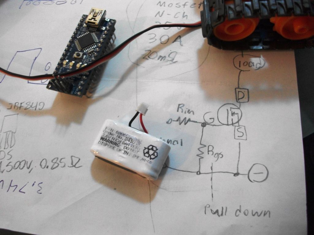
For this battery the easiest charging method is to connect gator clips to the outputs of a 1.5-9V NiCd charger, and to the leads of the battery. See the wiring diagram in step 4 for how this can be accomplished when assembled.
Step 4: Construction: Connect the wires to the socket
A socket is used to mount the Arduino Nano to the robot, besides making the Arduino removable so that it can be used for other projects, this simplifies attachment to the rest of the machine. Alternatively you could buy a small breadboard for $4 (as shown in the second picture below from sparkfun.com) and zip tie it to the top in a similar way for more modular design.
In my case I wired the servos into D11 and D10, but you could use any of the PWM outputs, as shown in the first picture below. I then wired the battery to a free pin on the socket in between pins that I wired to the power for the arduino (Vin) and the servos, so that I could switch them on and off with jumpers. I smashed the legs of the socket outward so they are easy to access for expansions. Notice that this placement also makes the USB connection and reset buttons easily accessible, at the end of the robot.
To charge the battery, power can be applied by putting the jumpers in the off position (stored on the other side of the socket) and plugging charging leads into battery +, and ground. Again, for this battery the easiest charging method is to connect gator clips to the outputs of a 1.5-9V NiCd charger. If you are using a different type of battery charge accordingly.
Step 5: Construction: Assemble the microbot
Here is where the eraser comes in. If you have the assembled servo/wheel sets from step 2, you can put the belts on them with the servo that has a wire coming from the side upright and the other laying with its long end pointed toward the upright one, as shown in the fist picture. Pull them to light tension, so the belts are nearly flat but not taught, and measure the gap between the servos. Cut a section of eraser to wedge in this gap. This works like suspension, allowing the frame some flexibility while holding it in place under most forces it will encounter. It’s the white part in the picture.
The battery fits in the crook between the upright and flat servos and the socket sits on top (second picture). Make sure the sockets legs are smashed outward for easy access. Then use one or two zip ties to strap the whole thing together, be sure the buckle is on the front or back, not underneath or above the socket, you don’t want it to get in the way of ground clearance or plugging in the Arduino. If you are using the mini-breadboard variant, you may need to file the middle channel a bit deeper for the zip tie to set in.
Finally, plug in that Arduino (third picture), you can make the jumpers by simply bending some stripped wire with pliers.
- How are the servos modified for continuous rotation?
Cut the potentiometer wires, solder resistors (about 1k to 10k, 5k used) between side pads and middle pad, remove the pot stop, and reassemble. - What parts of the Tamiya track hubs need drilling?
Drill the drive wheel cap for the mounting bolt and ream the hub center to fit the servo spline, stepping up drill sizes until tight. - How is the battery pack made?
Use four 1.2 V NiCd cells folded and taped into a pack (~4.8 V), or use a LiPo and charger if available; fold cells to fit the chassis and wrap in electrical tape. - How are the Arduino and power connected to allow charging?
Wire servos to PWM pins (example D11 and D10), wire battery and Vin through the socket with jumpers to switch power; remove jumpers and attach charger clips to battery + and ground to charge. - How is the robot assembled into a chassis?
Place two modified servo/wheel sets with tracks, wedge a cut eraser between them for spacing and suspension, fit battery in the crook, mount the 40-pin socket on top, and secure with zip ties. - Which Arduino pins are used for servos in the example?
The example wires the servos to D11 and D10 but notes any PWM outputs may be used. - How is the idler wheel attached?
Attach the idler using a Tamiya kit screw or suitable screw that does not pinch the wheel; tighten just enough to hold it without binding. - Do the servo cases require modification besides electronics?
Yes, cut a hole in the back half opposite the spline to mount the idler and remove mounting flanges, filing or sanding ridges flat.