
Summary of CCTV camera controller
This article describes a DIY CCTV switchbox project enabling connection of up to six cameras to a single screen using SPDT/SPST relays. It features dynamic sweep and static modes controlled by buttons or DCC addresses (950–956). Servo-controlled pan arms for the first three cameras are adjustable via a potentiometer in static mode. The system uses an Arduino with two code files: one for EEPROM initialization and another for control logic, alongside a TinyCad schematic.
Parts used in the CCTV Switchbox:
- Relays (SPDT or SPST)
- Potentiometers (two units)
- Buttons (F1 and F2)
- DCC Central Controller
- Servo motors (for cameras 1-3)
- Arduino microcontroller
- TinyCad software
- EEPROM memory module
This project allows you to build you own CCTV switchbox, that you can use to connect up to 6 cameras to a single screen.
The camera signal (CVBS over CInch or any other) is switched to the output using SPDT or even SPST relays.How it works ?
– by default the controller will cycle through all 6 channels at a speed which is adjustable by a potentiometer. This controls the time which each of the cameras’ image is displayed.
– if you press the “F2” button, the display will change to “static” mode and the last shown channel will remain active
– in Static mode, the F1 button will cycle through the 6 channels, displaying each of the corresponding images on screen until you press F1 again
– going back to Dynamic mode (sweep) is done by pressing F2 again
– if you want to control this from a DCC central, the addresses 950…956 are in use
950 = SWEEP mode
951..956 = camera 1..6
Cameras 1..3 can be mounted on Servo controlled pan/sweep arms and the position of those servos is controlled by the 2nd potentiometer. Changing the position of the servos only works in Static mode.
The camera signal (CVBS over CInch or any other) is switched to the output using SPDT or even SPST relays.How it works ?
– by default the controller will cycle through all 6 channels at a speed which is adjustable by a potentiometer. This controls the time which each of the cameras’ image is displayed.
– if you press the “F2” button, the display will change to “static” mode and the last shown channel will remain active
– in Static mode, the F1 button will cycle through the 6 channels, displaying each of the corresponding images on screen until you press F1 again
– going back to Dynamic mode (sweep) is done by pressing F2 again
– if you want to control this from a DCC central, the addresses 950…956 are in use
950 = SWEEP mode
951..956 = camera 1..6
Cameras 1..3 can be mounted on Servo controlled pan/sweep arms and the position of those servos is controlled by the 2nd potentiometer. Changing the position of the servos only works in Static mode.
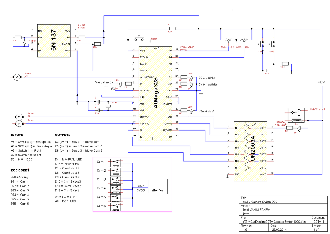
The schematic diagram
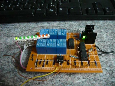
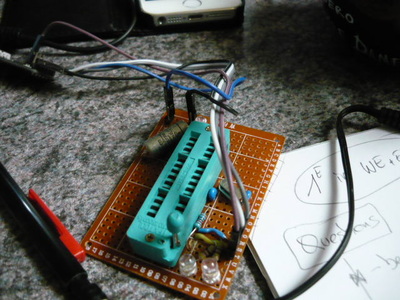
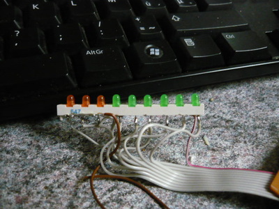
Physical build pictures.

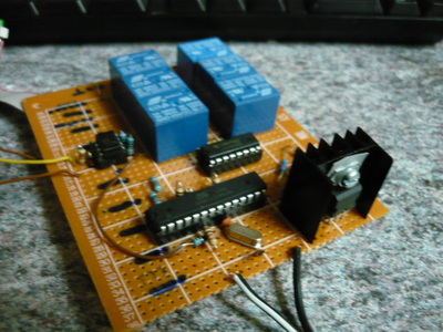
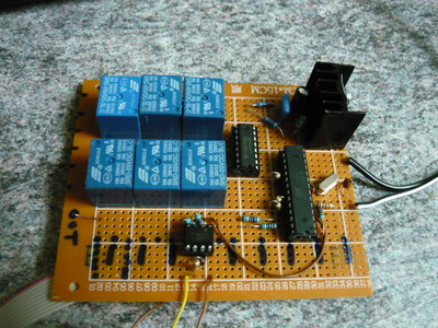
Arduino Code and TinyCad design file.
Notes :
*** the DSN file is the electronic schematic for the project as drawn in TinyCad
*** the first INO file is the Arduino code (use the Arduino SDK ) that will init the EEPROM data before first use. You can ignore this if you want, but the EEPROM will not be properly initialized and the program may not work correctly the first full loop but afterwards it will work fine en remember the last active channel in EEPROM even if you switch off the power for a longer period of time.
*** the second INO file is the actual control program.
*** the DSN file is the electronic schematic for the project as drawn in TinyCad
*** the first INO file is the Arduino code (use the Arduino SDK ) that will init the EEPROM data before first use. You can ignore this if you want, but the EEPROM will not be properly initialized and the program may not work correctly the first full loop but afterwards it will work fine en remember the last active channel in EEPROM even if you switch off the power for a longer period of time.
*** the second INO file is the actual control program.

| cctv_camera_switch_dcc.dsn |
| initeeprom_cctv.ino |
| dcc_cctv_control.ino |
The project in action (movie link).
Video 1 : the essentials… startup and sweep mode :
https://www.youtube.com/watch?v=urqqzoVGGIs&feature=youtu.be
Video 2 : the result on screen
* under construction *
- How many cameras can this project connect?
The project allows you to connect up to 6 cameras to a single screen. - Can I control the camera switching manually?
Yes, pressing the F2 button switches between dynamic and static modes, while F1 cycles through channels in static mode. - What is the default behavior of the controller?
By default, the controller cycles through all 6 channels at a speed adjustable by a potentiometer. - How do I control the device from a DCC central?
You can use addresses 950 for sweep mode and 951 through 956 for selecting specific cameras 1 through 6. - Can the first three cameras be moved automatically?
Yes, cameras 1 through 3 can be mounted on servo-controlled pan/sweep arms controlled by the second potentiometer. - Does the system remember the last active channel after power loss?
Yes, if the EEPROM initialization file is used, the program remembers the last active channel even after switching off the power. - What happens when I press the F2 button again?
Pressing F2 again returns the display from static mode back to dynamic sweep mode. - Which software is used for the electronic schematic?
The schematic diagram is drawn using TinyCad software and saved as a DSN file.
