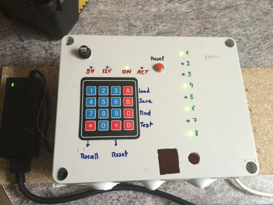
This light control box allows you to control up to 8 channels of mains power, which can be used to rutn on/off light elements or groups.
The purpose in my layout is to control LED spotlights (GU10 on 220V AC) that highlight specific sections in my layout.
You can use this to control other elements than light , too. But you may need to upgrade the relays or use optocouplers and Triacs, then.
The reason this has a DCC connection point is because I did not just want to be able to turn light on and off from the actual switchbox, but also through the train central control unit, so I have all the control in one place. This also allows linking to the PC and controlling it with home written software or even controlling if from within existing train control software. You could for example have a train run through your entire layout and “follow” it by turning on and off the spotlights of the sctions where the train actually passes. This can become a nice “showcase” for the special attractions on your train layout and you can amaze visitors by the spotlight following the train around automatically.
The way this works is simple:
* by pressing any of the keys 1..8 you immediately activate/deactivate the corresponding channel (these toggle on/off)
* by pressing the “0” key, you switch ALL lights OFF
* by pressing the “9” key, you switch ALL lights ON
* the “*” key recalls the last config (= “undo” key)
* the “#” key performs a “soft system reset”
* “A” = Load preset pattern from EEPROM memory
* “B” = Store current setting in to preset EEPROM
* “C” = Go to random mode (switch light groups on and off randomly at various durations)
* “D” = Run a “test loop”, switching on all channels one by one 1..8 and off again
If you want to control the light using your DCC central, here are the corresponding addresses to control :
900 = 0 (all off)
901 … 908 = 1…8 (toggle channels on/off by writing values “1” or “0”)
909 = 9 (all on)
910 = *
911 = #
912 = A
913 = B
914 = C
915 = D
Programmer’s note : this program requires the following Arduino libraries. Links can be found in the “tools and resources” section :
— EEPROM.h (standard for Arduino environment)
— DCC_Decoder.h
— Keypad.h
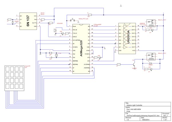
The schematic diagram
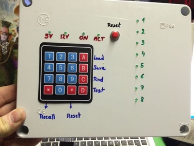
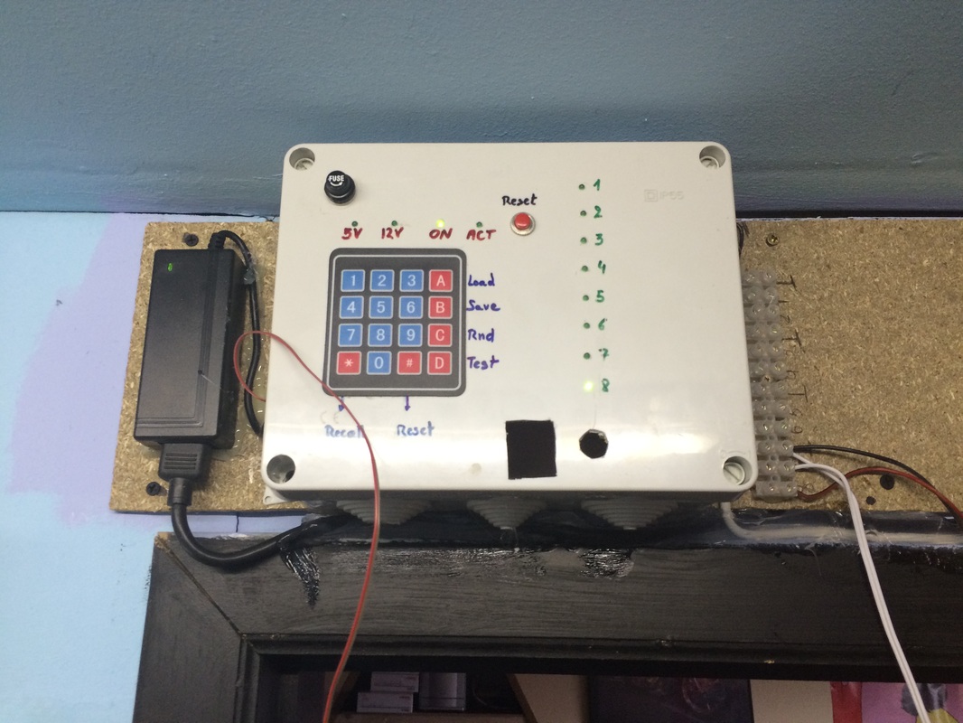
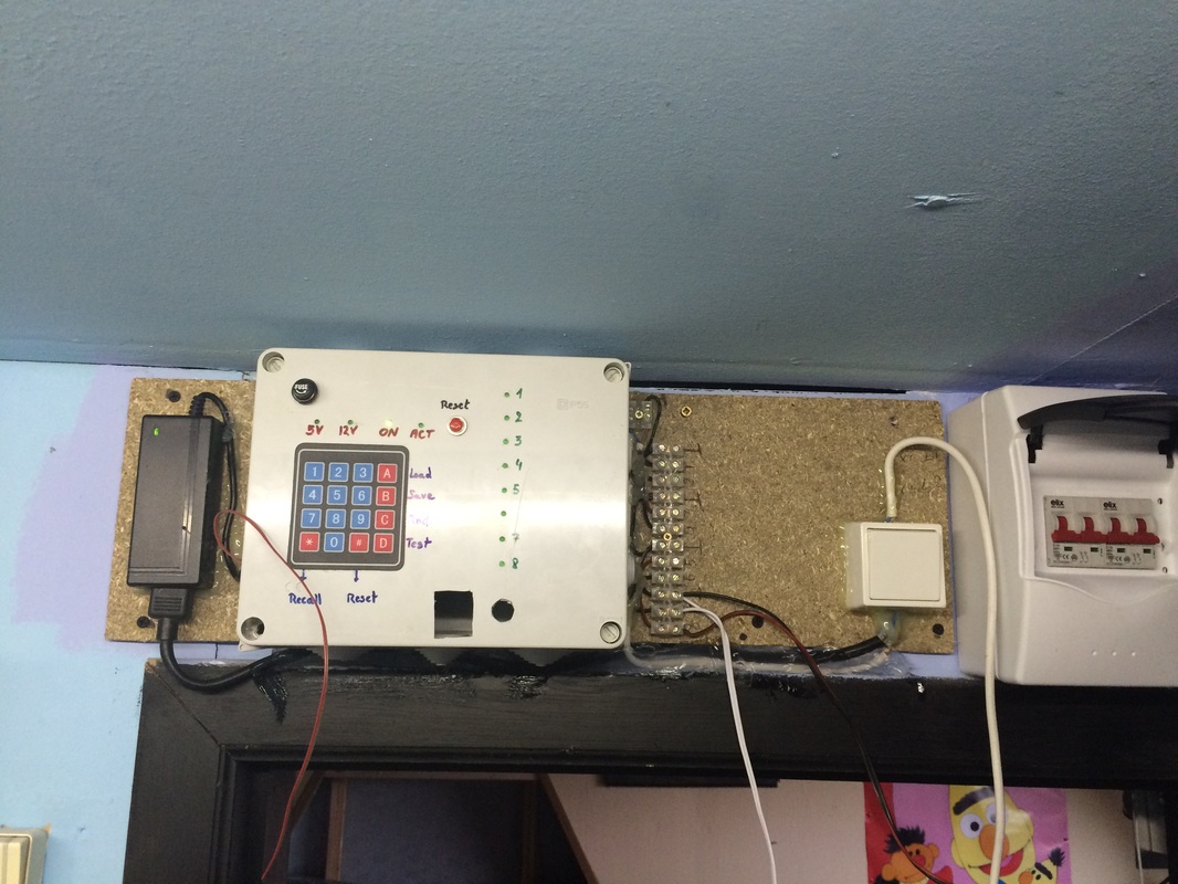
Physical build pictures
Arduino code and TinyCad design file
![]()
| dcc_kamerverlichting_16keys.ino |
![]()
| lichtsturing_keypad_dcc.dsn |
The project in action (movie link)
* a video of the initial testing . It works okay as long as a maximum of 2 channels are enabled. However, if more than 2 are being enabled, the system starts to do random output changes. The cause : using a UN2003 is not sufficient to control 8 micro relays. I will have to replace the UN2008 with 8 separate drivers for the relays. Driver = a transistor, a reverse current diode, and optionally an LED between the Arduino output and the relay coil. His is what is in the UN2008 but the IC can not handle more than 2 relays in terms of total current and power dissipation. To be continued .