Summary of Autonomous Control of RC Car Using Arduino
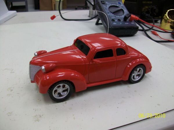
This article details how to convert a budget RC car into an autonomous vehicle controlled by an Arduino microcontroller. The process involves disassembling the car, removing its original controller chip, and soldering wires with resistors to specific PCB pins. This setup allows the Arduino to manage driving patterns, stunts, and future sensor integration like line following or sound detection.
Parts used in the Autonomous Control of RC Car Using Arduino:
- RC Car (inexpensive model)
- Arduino Duemilanove
- 4 1000 Ohm 1/8 Watt resistors
- 1/16th inch heatshrink tubing
- 22 AWG solid wire (Black and White)
- Solder
- 2 rubber bands
- 9V battery clip for Arduino
This instructable shows how to modify an inexpensive RC car so it can be controlled by an on-board microcontroller. You can program the controller to make the car do any number of driving patterns and stunts. Once you have the car being controlled from the on-board controller, you can add sensors for light and sound and make the car do things like line following.
Step 1: Gather Materials and Tools
I used the following materials:
-RC Car – el cheapo from Walmart. It cost $6 at my local Walmart.
-Arduino – I used the Duemilanove purchased from Sparkfun, (www.sparkfun.com)
-4 1000 Ohm 1/8 Watt resistors (color code BRN/BLK/RED). The value of the resistors is not critical. Anything within 50% should work.
– 1/16th inch heatshrink tubing to insulate the resistors after they’re installed
– 22 AWG solid wire. You’ll need five wires, 6 to 8 inches long. I used Black for the Ground and White for the 4 control wires.
– a small amount of solder
– 2 rubber bands
– 9V battery clip that plugs into the Arduino, also available from Sparkfun
Tools you’ll need are:
– small (not tiny) Phillips screwdriver
– wire stripper
– soldering iron
– “third hand” to hold resistors while soldering wires to them
– small tip diagonal wire cutters
– desoldering tool or braid
– tweezers or small needle-nose pliers
Step 2: Disassemble the Car
For this step, you will take the car apart. First, clip off the antenna using a strong pair of cutters. Then, remove the four screws that hold the body on the chassis and separate the body from the chassis. Next, remove the two screws that hold the internal electronics cover. Discard this cover.
Step 3: Remove the Antenna
Remove the screw holding the antenna. Cut the antenna wire near the printed circuit board being careful to only cut the black antenna wire. Discard the antenna and antenna wire.
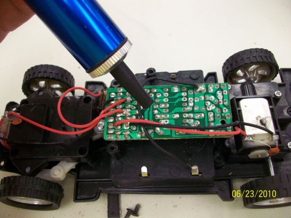
Step 4: Hack Into The Car’s Electronics
Unscrew the single screw holding the printed circuit board (PCB) to the chassis. Carefully turn the PCB over and screw it back down temporarily. Now, using small tip wire cutters, carefully clip each lead on the controller chip. Be sure not to cut any other leads or wire on the PCB. Remove and discard the controller chip.
Step 5: Connect the Wires
Flip the PCB back over. Using a solder sucker or solder braid, unsolder and clean out the holes for pins 2,6,7,10 & 11. Be careful not to use too much heat to avoid damaging the PCB. Prepare four resistor/wire assemblies as follows: Solder solid 22 gauge white wire to a 1K Ohm resistor. Make a total of four of these resistor/wire assemblies.
Insert and solder the resistor leads (the ones not connected to the wire) into the holes for pins 6,7,10 & 11. After soldering, slip a piece of shrink tubing over the wire all the way down to the PCB. Shrink the tubing with a match, lighter or tubing shrinker.
Install and solder a solid black wire into the hole for pin 2.
Mark the white wires with stripes so you’ll know which wires control the different functions.
1 stripe – Left signal – pin7;
2 stripes – Right signal – pin 6;
3 stripes – Reverse signal – pin 10;
4 stripes – Forward signal – pin 11;
-Arduino – I used the Duemilanove
-4 1000 Ohm 1/8 Watt resistors
For more detail: Autonomous Control of RC Car Using Arduino
- How can I make my RC car perform driving patterns?
You must modify the car so it is controlled by an on-board microcontroller like an Arduino. - What is the best way to insulate the resistors after installation?
Slip a piece of 1/16th inch heatshrink tubing over the wire all the way down to the PCB and shrink it. - Can I use resistors with different values than specified?
Yes, the value is not critical as long as they are within 50% of the required resistance. - Which pins on the PCB need to be cleaned out for new connections?
Pins 2, 6, 7, 10, and 11 must be unsoldered and cleaned using a solder sucker or braid. - What color wire controls the forward signal?
The white wire with four stripes connects to pin 11 to control the forward signal. - How do I identify which wire controls the left signal?
The white wire with one stripe connects to pin 7 to control the left signal. - Does this project allow for adding sensors later?
Yes, once controlled by the microcontroller, you can add sensors for light and sound. - What tool is recommended to hold resistors while soldering?
A third hand tool is needed to hold resistors while soldering wires to them.