So one of my last projects was adding a weather vane to my Arduino weather station.
https://www.instructables.com/id/Arduino-Wind-Chill-Machine/
https://www.instructables.com/id/Arduino-Weather-Station-Part2/
This Lazy Old Geek decided to add a rain gauge to it even though we don’t get much rain in the high desert. Most digital rain gauges are based on something called a tipping bucket. Here is a good diagram complements of:
http://park18.wakwak.com/~weather/archive/RainGauge.htm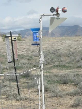
There are actually a lot of rain gauges for sale. Amazon.com has some tipping buckets for around $20. But I’m a Geek where’s the challenge in that, so I decided to build my own.
Step 1: Parts List
Parts List:
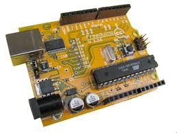
USB Freeduino (Arduino-clone) $22.50
Adafruit Data logging shield $19.50
http://www.adafruit.com/index.php?main_page=product_info&cPath=17_21&products_id=243
SD Card $ 6
Aluminum NoTrespassing Sign $ 2
2 Ethernet Couplers $1.40 (ebay.com)
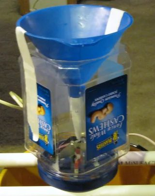
1 empty Cashew nut plastic jar
1 Funnel (5.5″ diameter) dollar store
1 ¾” pipe strap $ 0.59
2 #8 nylon washers $ 0.17 @
1 small magnet (10 for $1 at Harbor Freight)
Honeywell SS461C Hall Effect IC $1.86 Digikey
Prices US dollars March 2011
Useful Tools:
Drill/drill press
Rotary tool (Dremel/clone)
Syringe ($0.99)
Any USB Arduino should work but it is easier to wire it up to an Arduino shield so the clone would have to be shield compatible. There are some good deals on ebay for Arduino Duemilanove 2009 for about $18.
The syringe is actually a cattle syringe for veterinarian use. I am a vet, close enough. Actually, this worked pretty good for calibrating my rain gauge.
Step 2: Rain Gauge Design
Solution: So I did some research on tipping buckets. How they work is that the funnel is over one of the buckets. Rain drips into the funnel and into one of the buckets. After a certain amount of water, the weight of the water tips the bucket so the other bucket is under the funnel and the reed switch is triggered and sends a count to the circuitry. As the rain continues, the other bucket fills up and tips it the other way again triggering the reed switch.
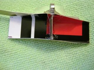
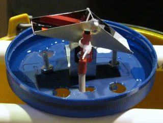
To make my tipping bucket, I took a piece of the aluminum ‘NoTrespassing’ sign, I used for my weather vane. I marked a rectangular piece 3” x 2.25” as shown in the diagram. I cut it with a pair of scissors and folded up the sides. I happened to have a piece of ¾” aluminum, I used to shape the trough and bent the sides up. Then I trimmed the sides so they were triangles. I cut another aluminum piece ¾” square, rounded the bottom corners and hot glued it in the middle so that you have two ‘buckets.’ See first picture.Warning: If you are a horrible hot-gluer like I am, it might leak. Mine did. Pour a little water in the side tilted up and see if it leaks out the other side. If it does, heat up the joints and/or add more hot glue. You can see from my pictures what a terrible job I did but it stopped leaking.
The next picture looks a little weird. I wanted to use nylon spacers for the pivot point but my local Ace hardware didn’t have any. They did have these #8 nylon washers that are about 1/8” thick so I bought them. I wanted the spacers to stick out away from the sides of the tipping bucket so I taped another scrap of the sign to the tipping bucket then I tapped the washer so that it was flat with the scrap. The adhesive tape looks pretty weird in this picture. Then I hot glued the washer to the bottom of the bucket assembly and did the same to the other side.
The next picture shows the results. Again you can see my poor hot-glue skills and yes, it’s a little crooked but it worked okay.
Step 3: Mounting Bracket & Container
Problem: So my local Ace hardware had some angle brackets but they were a bit expensive and I had no idea what size I would need.
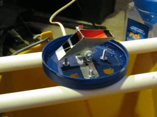
Solution: So I decided to make my own. Perusing the store I found these ¾” pipe straps. Actually, I found some in plumbing and electrical but electrical was a lot cheaper. So I took the strap and flattened it out in my vise. Then I bent a right angle with about 1 1/8” sticking up (see picture). In the bottom of the strap about ½” from the angle, I drilled 5/32” hole for #8 hardware. This was rather specific in that it was close to the center of where the tipping buckets would be. Then I drilled another 5/32” hole for a second bolt. I also had to trim off some of the bracket with tin snips so it would fit in the nut jar lid.
Problem: Now I started looking around for something to put the rain gauge in. My first thought was plastic plant pots. But thinking ahead (for a change) I thought I’d want something transparent so I could get it lined up and make sure it was working correctly.
Solution: Well, I decided on an empty plastic 2lb 6oz nut jar. Now most people would think, take the lid off and build the tipping bucket inside the jar. With my sometimes inverted logic, I decided to build the bucket in the lid and cut a hole for the funnel in the bottom of the jar.
So that is why I drilled the angle strap for the center of the tipping bucket. I drilled a hole in the center of the lid (conveniently, it was dimpled there anyway), Then with a screw holding it, I drilled the second mounting hole in the lid. So with the funnel ‘centered’ in the jar, the tipping bucket should be right under it. Now I also drilled two holes about 1” from the center at right angles to the bracket for ‘calibration’ screws underneath the tipping buckets. I also drilled four big holes to allow the water to drain off. I think all of the parts, so far, are galvanized so should not be subject to rust or water damage.
The funnel I selected is 5.5” diameter. One of the traditional rain gauge funnels is 8” but this one fit my jar better. I forgot to take a picture before I put it in the jar but I wrapped a piece of plasticized paper (plastic on one side) so that the bottom of the funnel is smaller and easier to align over the tipping buckets.
I used a Dremel-clone to cut the opening for the funnel. Conveniently, there was a circular indentation in the bottom of the jar.
Step 4: Electrical Design
Problem: So how should I do the electronics? The traditional way is to use a reed switch. For those of you not familiar, reed switches are little glass tubes with two electrical contacts that close in the presence of a magnet. Well, I’ve worked with them before. They are a little fragile, hard to attach and I didn’t have any anyway. Next I thought of optical switches. I had a bunch of these from scrapped out printers. But I couldn’t figure out a good way to activate them with my buckets and keep moisture out at the same time.
Solution: Well, I had some left over hall effect switches.
Technospeak: I haven’t worked much with hall effect switches but I was under the impression that there were two types: One that closes whenever a magnet is near but opens when the magnet goes away. The other is a latching type that closes when a certain pole (south) is near than opens when the opposite pole (north) is near. Well, I thought I had bought both types but being OLD I couldn’t figure out the specifications. Anyway, both the types I have are apparently of the latching variety.
Using the Old innovator brain, I hot-glued one of my leftover magnets on its edge so one pole is on one side and the other on the other. It doesn’t matter which one is where. With the hall switch in the middle, the output flips whenever the bucket flips. With a piece of scrap aluminum, I built a little bracket that attached the SS461C hall effect switch with a tie wrap. You can bend it so the sensor is closer or farther away but didn’t seem to be very critical.
Wiring the SS461C hall effect switch: I used some telephone cable to wire up the SS461C. The red wire is +5, the black wire is ground and the yellow wire is output (see picture). Then I took a piece of electrical tape to isolate the leads, then put some heat shrink over the whole assembly (see picture).
Attached is the schematic for Weather Station 3. The circles around the outside are the Arduino shield pins. I took a picture of my shield.
Step 5: Wiring/modifying Coupler
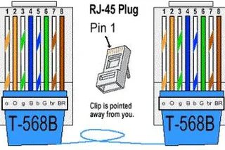
The next picture is the standard Ethernet cable, color-code and pinout. This is the color coding I used in my schematic.
This section is pretty hard to do and I wouldn’t recommend it for the inexperienced. As an easier alternative, the rain gauge can be directly soldered to the Weather Station 2 Ethernet cable.
Difficulty High: For Weather Station 2, I had an Ethernet coupler near the station. I decide to build a special coupler to tap in for the rain gauge. By carefully prying with an Xacto knife and small screwdriver, the coupler can (probably) be split apart. There are eight springy wires inside (I didn’t take a picture) that are bent up one end and down on the other to make contact with the standard Ethernet connectors. Now if you’re lucky, there may be actual wires connecting the two ends. Mine just had a continuous springy wire laid in a channel. I soldered a lead to pin 1 (Brown wire) and another to pin 2 (Brown-white wire). Be careful that they aren’t shorted to any other wires. I cut a hole in the plastic case for these two wires. I also bent one end of pin 8 (Orange-white) and punched a hole for it. Then I carefully closed the two halves. Now from the other end of the telephone cable connected to the SS461C, I connected the red wire to pin 1, the black to pin 2 and the yellow to pin 8. Then I carefully ohmmed out all of the connections and tested for any shorts. Then I hot glued the outside of the coupler. (See pictures)
With this setup, one side of the coupler has eight connectors, this side goes toward the Arduino. The side with seven connections goes to the rest of the weather station.
The advantage is that I can connect this anywhere in the cabling. For example, inside my house for calibration, then outside when ready to run.
Step 6: Calibration and Adjustment
Setup procedure:
I took a water pail, laid a couple of pieces of PVC across the top and put the tipping bucket over the PVC as shown in the picture. If not tested before, put some water in the syringe or any kind of liquid measuring device. Slowly add some water in the higher bucket.
First, make sure it doesn’t drip down into the other bucket. If it does re-glue it.
Second, keep adding water until it starts to tip. Make sure the water doesn’t spill over the sides before it tips. If it does, your pivot screw might be too tight or it might be binding somewhere.
Do the same for the other bucket.
Calibration procedure:
Reading syringe: Now my syringe has a cone shaped plunger so you may wonder where to read it. I’m not sure myself but it’s easier to read the bottom outer edge of the plunger. As long as you are consistent it won’t matter.
This is where the syringe makes it easier. Suck some water into the syringe to one of the marks perhaps 30 mL (milliliters). If you’ve had some medical experience, it’s probably good to get rid of any air bubbles. Hold the syringe with the tip up and snap it with your finger to knock loose any air and plunge it out the tip.
Once you have it set, carefully syringe water into the top cup until it tips over.
Look at the syringe and see what the level is at. Subtract this from the starting value to get how much water it takes to tip the bucket. Mine was about 5 mL. Do the same for the other side.
They should be about the same, but if you’re mechanical skills are like mine, they may not agree. You can adjust with the calibration screws. The screw on the left actually affects the bucket on the right and vice versa. I think raising the screw will increase the amount needed to tip the bucket.
Anyway, they should be about the same, the amount is not critical but I set mine for 5 mL. This value will be needed in the Arduino sketch.
Assembling the rain gauge. Now screw on the bottom of the nut jar onto the lid. Put the funnel into the hole and center it over the tipping buckets. My funnel had a fairly big opening at the bottom and it was pretty far from the tipping buckets. I had some pliable plastic paper, so I wrapped it around the funnel so the opening was smaller and just above the tipping buckets and taped it. Now you can move the funnel around so that it is centered over the buckets. I put some masking tape on the funnel and nut jar to hold it in place.
Caution: Remember that the alignment may change when the lid is tightened or loosened. It should be pretty close to the center of the jar and lid though so shouldn’t be a problem.
After some more testing with the syringe, I hot-glued the funnel to the jar.
Step 7: Installing Rain Gauge
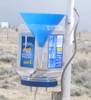
Solution: But the jar was squared and the edges pretty much cleared the funnel. There was still a little overlap but I had a step in my pole so it cleared. I could claim I had this all planned but it was just luck.Procedure:
Remove the lid from the jar.
Hold the bottom with the funnel and drill through the pole. I used some 3/8” nuts and bolts.
Drill through the nut jar.
Attach the nut jar with the hardware.
Drill the second hole and attach.
Screw the lid assembly onto the funnel assembly.
Attach the coupler or wire the rain gauge to the Ethernet cable.
Step 8: Arduino Sketch

So here is my Arduino sketch in a zip file. Weather3.zip.
This sketch is for the whole weather station using the Adafruit datalogger. So it may have to be customized to your own application.
Here is the relevant rain gauge code.
#define RainPin 5
//Rain variable
bool RainHigh=false;
const float LowAmt=5.0; //when rain is low, takes this ml to trip
const float HiAmt=5.0; //when rain is high, takes this ml to trip
float RainAccum=0.0; //Rain accumulator since start of sample
void setup(void) {
// Rain get start state
if (digitalRead(RainPin)==HIGH)
{
RainHigh=true;
}
else
{
RainHigh=false;
}
In setup, I determine if the RainPin is high or low. This just determines which bucket is up and the starting point to start counting tips of the bucket.
void loop(void)
{
// Rain calculator, looks for Rain continuously
// Look for low to high
if ((RainHigh==false)&&(digitalRead(RainPin)==HIGH))
{
RainHigh=true;
RainAccum+=LowAmt;
}
if ((RainHigh==true)&&(digitalRead(RainPin)==LOW))
{
RainHigh=false;
RainAccum+=HiAmt;
}
In the main loop, I look for a transition from the current state. If it occurs, then I add the correct amount of water. Now in my case, I have them both set at 5 mL.
My sketch sends RainAccum to the serial port and writes it to the SD every 10 seconds. I realize 5 mL doesn’t mean much and neither does the amount every 10 seconds but for my purposes it works.
Here are some calculations for the Rain gauge.
2.54cm = 1inch (exactly)
Diameter of collecting funnel is 5.5” or 13.97cm.
Area is Pi*R2 or Pi*D2/4 or 23.76 In2 or 153.28cm2
U.S. measures rain in inches so it would be 23.76In3 or 389.33cm3
Cm3 is the same as mL
So 1 inch of rain would be 389.33mL.
5mL is about 0.0128 inches of rain
Now, you can use the weather station with just the Arduino software using the serial monitor. Also the datalogger records the same data plus a date and time stamp to a CSV file.
Step 9: VB Express Software
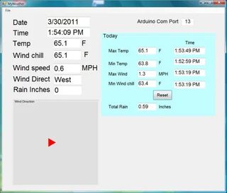
I’ve included the software in a zip file. Here is a screenshot.The program was written for M.S. Vista and requires a directory under documents called WeatherData. It may not work on other operating systems.
To install, copy the zip file to a directory. Make sure you have internet access, run setup.exe.
The main thing you have to do is determine which serial port your Arduino is connected to and type it into the Arduino Com Port textbox. Then it should run automatically. Make sure you don’t have the Serial Monitor open at the same time.
In the blue panel is maxs and mins for the day. (If Min Temp is zero, click on Reset button). The data is updated from the Arduino. I made a little graphic display to show wind direction. As speed increases the arrow gets longer.
Over to the left is a txtbox called Rain Inches. This generally won’t mean much as it only displays rain for the last 10 second sample. In the middle is the one that says Total Rain. This is the amount of rain for the day. I dumped some water in the collector to get a reading as I haven’t really had a chance to see it work with real rain.
Some day I hope to get some real rain to see how well this works. I have a glass rain gauge set next to mine so that I can compare the two. I might have to adjust my calibration.
Data is automatically stored to a MonDay.csv file in the WeatherData directory.
If you are experienced with VB Express, I can provide the source code so you can rewrite this to your liking. Leave me a comment.
Concerns: So I do have some concerns with my weather station.
1. I am using Ethernet cable outside but it is not rated for external applications. It could be damaged by rain, wind and sun.
2. The paper cone in the rain gauge is just held on by tape. I don’t know how it will do with sun and rain.
3. I built an anemometer many years ago, the bearings wore out. Of course this was in windy Boulder. With this design, it should be fairly easy to replace the bearing.
4. Static electricity could be a problem with the electronics especially with strong winds and dry conditions
Conclusions: While I don’t expect any/many readers to duplicate this project, I hope it provides readers with ideas on interfacing with the Arduino and some of it’s capabilities.
For more detail: Arduino Weather Station Part3, Rain