
Summary of Arduino Uno Xylophone
This article details the construction of an Arduino Uno xylophone that detects strikes on eight keys via piezo disks and a multiplexer, triggering MIDI sounds on a computer. The project optionally includes LED indicators for each key. It covers necessary hardware, software requirements like the Arduino IDE and Midi libraries, circuit assembly using protoboards, and physical construction within an acrylic box.
Parts used in the Arduino Xylophone:
- Arduino Uno
- 9 V battery with Arduino adaptor
- Arduino to USB connector
- 8 piezo disks
- 8 1 M Ohm resistors
- Protoboards (two separate boards)
- Terminal Connectors
- Strips of acrylic and a box
- Plenty of wire
- 16 LED lights
- Suitable resistor (220 Ohms used)
- Multiplexer
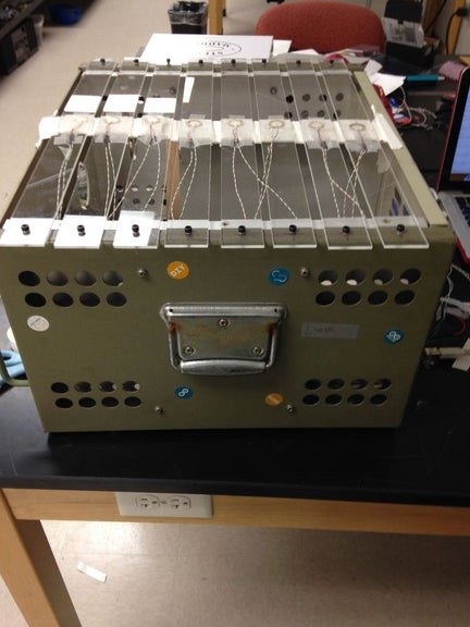
This xylophone uses the Arduino Uno and a multiplexer to identify when one of eight keys are struck, and play that sound via midi sound on a computer. An optional part of the instructions also allows each key to light up with two LED lights at the same time the xylophone is struck. These steps outline what I have done.
Step 1: Necessary Parts
- Arduino Uno
- 9 V battery with Arduino adaptor
- Arduino to USB connector
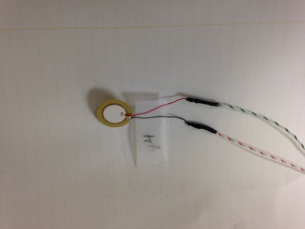
- 8 piezo disks
- 8 1 M Ohm resistors
- Protoboards
- Terminal Connectors
- Strips of acrylic and a box (or something to make the xylophone with)
- PLENTY of wire
Software:
- Arduino Environment
- Hairless Serial to Midi Converter
- Max MSP
- Max Patch (Attached, from Amanda Ghassaei)
- Arduino Midi Library
For LED Compatibility:
- 16 LED lights (two for each bar, cannot be more than two)
- Suitable resistor (I used 220 Ohms)
Step 2: The Basics
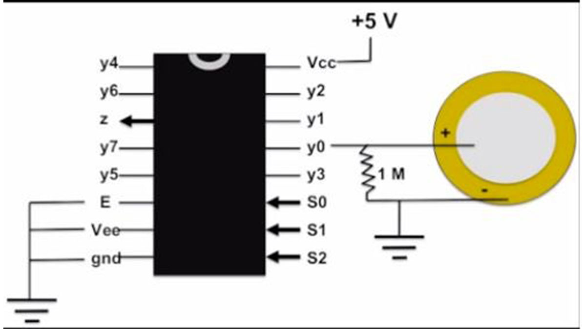
The multiplexer is key to this project, as it allows you to take 8 analog ins or outs, as opposed to the 6 on the Uno. Using one analog in and three digital ports on the Arduino, the multiplexer runs through each input and reads any changes. In this case, the multiplexer reads any change in the piezo disks. (Picture is courtesy of Jenna Deboisblanc)
Step 3: The Protoboards
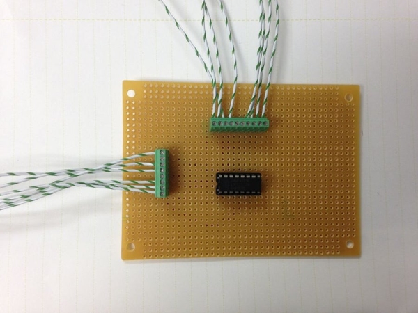
You will need two separate protoboards. One connects the multiplexer to the inputs both of the piezo and the Arduino Uno, and the other deals solely with the piezo disks.
Protoboard 1: Multiplexer
On the photo of the front of the board, the multiplexer connects to the 8 different positive inputs of the piezo disk on the top Terminal Connector. The side Terminal Connector connects the S0, S1, S2, A1, +5V, and Ground to the Arduino Uno. The back of the board is seen in the second picture (the piezo inputs are now on the bottom, and the Arduino connections are now on the bottom).
Protoboard 2: Piezos
Each piezo has a positive and a negative. The positive connects to a resistor which connects to ground, and the negative connects directly to ground. The mutual ground is connected to the same ground as on the multiplexer protoboard, and separate wires are soldered to each of the positive piezo wires and fed into the mutliplexer board.
Step 4: Assembly
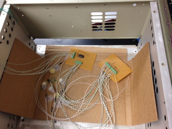
When you have your box and acrylic strips, you can begin assembly. First, put the protoboards delicately into the box, making sure metal does not touch. Then, begin attaching piezos to the acrylic strips with tape, and attach the strips onto the box, making your xylophone. You will likely want to put a steady object below the piezos to make the force of each hit stronger.
A note: be very careful with the Piezo disks. The attachment wires come off the plates easily, I would suggest soldering on new wiring.
Read more: Arduino Uno Xylophone
- How does the multiplexer function in this project?
The multiplexer allows the system to handle 8 analog inputs instead of the 6 available on the Uno by using one analog input and three digital ports to read changes in the piezo disks. - What software is required to run the Arduino Xylophone?
The project requires the Arduino Environment, Hairless Serial to Midi Converter, Max MSP, Max Patch, and the Arduino Midi Library. - How are the piezo disks connected to the protoboard?
The positive side of each piezo connects to a resistor which goes to ground, while the negative side connects directly to ground; separate wires from the positive sides feed into the multiplexer board. - Can I use more than two LEDs per bar?
No, the instructions specify that you can use two LED lights for each bar but cannot use more than two. - What is the best way to attach wires to the piezo disks?
Since attachment wires come off the plates easily, it is suggested to solder on new wiring for better stability. - How do you ensure a stronger hit force on the xylophone?
You should put a steady object below the piezos to make the force of each hit stronger. - Does the project support playing sounds via MIDI?
Yes, the xylophone identifies when keys are struck and plays that sound via MIDI on a computer. - What components connect the multiplexer to the Arduino Uno?
The side Terminal Connector links S0, S1, S2, A1, +5V, and Ground from the multiplexer to the Arduino Uno.
