Summary of Arduino UNO Tutorial 6 – Rotary Encoder
This article details an Arduino UNO tutorial for controlling LED brightness using a Sparkfun Rotary Encoder. It explains the quadrature signal principle (A and B phases) to determine rotation direction and speed. The project utilizes a 200Hz timer interrupt to sample pulse transitions, filtering switch bounce while incrementing or decrementing a counter that adjusts the PWM output. This method offers superior control over potentiometers by enabling precise step counting and variable speed detection.
Parts used in the Rotary Encoder Project:
- Arduino UNO microcontroller
- Sparkfun Rotary Encoder
- LED
- Timer interrupt mechanism
We have written a tutorial for Rotary Encoders using a Microchip microcontroller but now would be a good time to make an Arduino UNO version.
With a rotary encoder we have two square wave outputs (A and B) which are 90 degrees out of phase with each other. The number of pulses or steps generated per complete turn varies. The Sparkfun Rotary Encoder has 12 steps but others may have more or less. The diagram below shows how the phases A and B relate to each other when the encoder is turned clockwise or counter clockwise.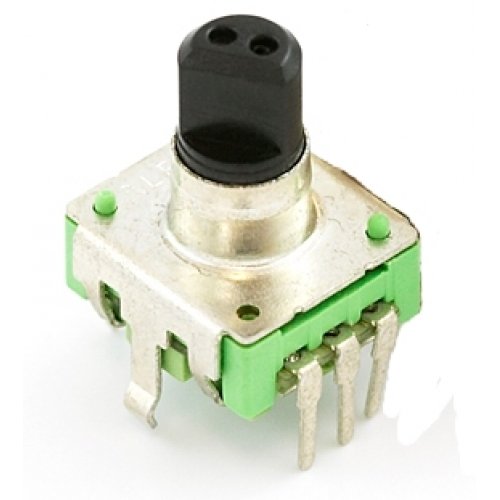 Every time the A signal pulse goes from positive to zero, we read the value of the B pulse. We see that when the encoder is turned clockwise the B pulse is always positive. When the encoder is turned counter-clockwise the B pulse is negative. By testing both outputs with a microcontroller we can determine the direction of turn and by counting the number of A pulses how far it has turned. Indeed, we could go one stage further and count the frequency of the pulses to determine how fast it is being turned. We can see that the rotary encoder has a lot of advantages over a potentiometer.
We will now use the rotary encoder in the simplest of applications, we will use it to control the brightness of an led by altering a pwm signal. We will use the easiest method to read the encoder, that is the use of a timer interrupt to check on the values.
We will use the sparkfun encoder as discussed above. The first thing is to determine how fast we need our timer to operate. If you imagine that at best we could turn the encoder through 180 degrees in 1/10th of a second, that would give us 6 pulses in 1/10th second or 60 pulse per second. In reality its never likely to be this fast. As we need to detect both high and low values this gives us a minimum frequency of 120Hz. Lets go for 200Hz just to be sure. (Note: as these units are mechanical switches, there is the possibility of switch bounce. Using a fairly low frequency allows us to effectively filter out any switch bounce) Each time our timer code triggers, we compare the value of our A pulse with its previous value. If it has gone from positive to zero, we then check the value of the B pulse to see if it is positive or zero. Depending on the outcome we can increment of decrement a counter. We then use this to control the PWM value to increase or decrease the brightness of the LED
And the source code for the sketch is shown below. It builds on the previous tutorial where we used the millis() function to give us a timing interval. We use the same idea here but use 5ms as the elapsed time check (5ms = 200Hz). Hopefully, the code should be easy enough to understand and easily modifyable to put the Rotary Encoder to other uses.
For more detail: Arduino UNO Tutorial 6 – Rotary Encoder
- How do you determine the rotation direction of the encoder?
By checking if the B pulse is positive when the A signal goes from positive to zero for clockwise turns, or negative for counter-clockwise turns. - What is the recommended timer frequency for this project?
A frequency of 200Hz is chosen to ensure detection of both high and low values and to filter out mechanical switch bounce. - How does the code detect the number of steps turned?
The code counts the number of A pulses and increments or decrements a counter based on the direction determined by the B pulse value. - Can this setup measure how fast the encoder is being turned?
Yes, by counting the frequency of the pulses, one can determine the speed at which the encoder is being turned. - Why use a rotary encoder instead of a potentiometer?
Rotary encoders offer advantages such as determining direction, counting exact steps, and measuring rotation speed. - What function replaces millis() in the timing logic?
The code uses a 5ms elapsed time check, which corresponds to the 200Hz frequency required for the timer interrupt. - How is the LED brightness controlled in this application?
The brightness is altered by modifying the PWM signal based on the value of the incremented or decremented counter. - What causes switch bounce and how is it handled?
Switch bounce is caused by mechanical switches; it is effectively filtered out by using a relatively low timer frequency of 200Hz.