Description
In this tutorial you will set up and turn on a single LED. Note that this code can actually be executed with just the Arduino and no other components as in Figure 5. If you notice, next to pin 13 is a tiny LED on the board. If you execute the code below, you should see that LED turn on.
Note: In the photos/video you will see me use a 1.2kΩ resistor. I did this to back off the brightness for the camera. The actual value of the resistor is not critical, larger values will create more dim light, smaller values will create a brighter light. We’ll talk more about resistors later.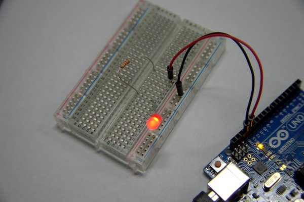
You will need
- 1x Arduino UNO
- 1x 220Ω (Ohm) Resistor (red, red, brown)
- 1x Single color LED
- 2x Hookup Wires
Setup
See the video below to watch the circuit being set up.
- Connect one wire from GND on the Arduino (any GND will work, I used the one next to pin 13) to the breadboard’s negative/ground path. Often times this will be the long vertical path down the edge of the board. It might be marked with a black or blue line. Get in the habit of using these paths on the breadboard for your ground and voltage sources.
- Connect another wire from pin 13 to any horizontal channel on your breadboard.
- Connect the resistor from the channel you connected to pin 13 to any other channel (but not the same one).
- Connect the long end of the LED to the end of the resistor (the one not connected to pin 13). Connect the short end of the LED to the GND channel of the breadboard.
Illustrations
Code
{
pinMode(ledPin, OUTPUT);
digitalWrite(ledPin, HIGH);
}void loop()
{
}
1 2 3 4 5 6 7 8 9 10 11 | int ledPin = 13; void setup() { pinMode(ledPin, OUTPUT); digitalWrite(ledPin, HIGH); } void loop() { } |
Line 1: Declare a variable that indicates which pin the LED is connected to.
Line 5: Tell the Arudino that you wish to output voltage on that pin
Line 6: Tell the Arduino to actually output a full 5V the LED
Line 9: The loop method is required in all Arduino programs but we will leave it empty. Later on this will be used to make things happen over and over again.
Try setting the pin to “LOW”. This should turn the LED off.
Downloads
Theory
This is a more modern take on the traditional battery + light bulb circuit. In reality, when you are working with this circuit, the battery is actually your computer + Arduino. Your computer (or battery/wall wart) is supplying the electricity and the Arduino is making certain that the LED gets exactly 5V no matter what power you supply. The LED + Resistor is acting like the light bulb.
There is one major difference between the traditional circuit and this circuit. As you may know, LED stands for Light Emitting Diode. A diode in simple terms is a device that allows current to travel in one direction and blocks it from travelling in the other direction. Diodes are often used to protect circuits that could be damaged if the voltage went in the wrong direction. We’ll talk a lot more about diodes later. By comparison, a light bulb is a “Light (and heat) emitting resistor”. While they have similar results, they work in very different ways.
In our case, the resistor is a protective component. It lowers the voltage in the circuit that is supplied into the LED. Depending on your actual LED, you might be able to bypass it but I wouldn’t risk it. If the voltage exceeds what your LED can handle you will see it light it very brightly and then poof, magic smoke. If you have LEDs to spare, try connecting one directly to a 9V battery with no resistor. Note: There are some LEDs that are rated to handle higher voltage but they are not the kind we are using.
This tutorial expands on the first tutorial by making your LED turn on and off.
Setup
Set up your project exactly the same as #1. The only change will be the code we send to the Arduino.
Video
Blinking an LED
Code
{
pinMode(ledPin, OUTPUT);
}void loop()
{
digitalWrite(ledPin, HIGH);
delay(500);
digitalWrite(ledPin, LOW);
delay(500);
}
1 2 3 4 5 6 7 8 9 10 11 12 13 14 | int ledPin = 13; void setup() { pinMode(ledPin, OUTPUT); } void loop() { digitalWrite(ledPin, HIGH); delay(500); digitalWrite(ledPin, LOW); delay(500); } |
Line 1: Declare a variable that indicates which pin the LED is connected to.
Line 5: Tell the Arudino that you wish to output voltage on that pin
Line 10: Tell the Arduino to actually output a full 5V the LED (turning it on)
Line 11: Wait for 500 milliseconds (half a second)
Line 12: Tell the Arduino to output 0V to the LED (turning it off)
Line 13: Wait for 500 milliseconds (half a second)
Lines 10-13 will be repeated indefinitely as long as the Arduino is powered.
Theory
The loop method gets executed on the Arduino as fast as it possibly can. It will continue to execute until you reset or power off the device. Depending on how much work each loop must do, it could execute this method several thousand times per second, much faster than the human eye can see. As a result, if you omit the delays, your LED will appear to stay lit up. If you could put a high speed camera on it though, you will observe that it actually is turning on and off very quickly.
LEDs can turn on and off very quickly. Try staring at a light bulb as you turn it on and off, you can actually perceive the light getting brighter and darker as you flip the switch. An LED though can go from fully off to fully on in a near instant. The end result of alternating on/off quickly though, to our eyes, is the light is less bright. Omitting the delays will therefore, make the light appear not quite as bright as allowing it to stay on for a full half second (500 milliseconds).
Set up your project exactly the same as #1.
Code:
{
pinMode(ledPin, OUTPUT);
}void loop()
{
for (int i = 0; i < 255; i++)
{
analogWrite(ledPin, i);
delay(30);
}
for (int i = 255; i >= 0; i–)
{
analogWrite(ledPin, i);
delay(30);
}
}
1 2 3 4 5 6 7 8 9 10 11 12 13 14 15 16 17 18 19 20 21 | int ledPin = 11; void setup() { pinMode(ledPin, OUTPUT); } void loop() { for (int i = 0; i < 255; i++) { analogWrite(ledPin, i); delay(30); } for (int i = 255; i >= 0; i–) { analogWrite(ledPin, i); delay(30); } } |
Line 1: Declare a variable that indicates which pin the LED is connected to.
Line 5: Tell the Arudino that you wish to output voltage on that pin
Lines 10-20: Two loops, the first increasing the voltage from 0V to 5V and the second decreasing the voltage from 5V to 0V. Note that we use analogWrite this time which lets us set the voltage in 8 bit resolution (0 to 255). These loops happen very quickly, so we delay each step by 30 milliseconds so that we can see the fade happen.
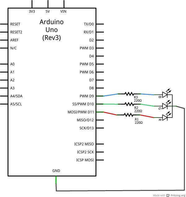
You will need:
1) Arduino
2) 3x 220 Ohm Resistor
3) 1x Common Cathode RGB LED
For more detail: Arduino LEDs