Summary of Arduino Touch Screen Room Control
Overview of touch panel project for bedroom wall: A touch-screen control panel (Arduino Mega with touch shield and Netduino) provides infrared TV control (power, volume, mute, input) and RF-controlled outlets (two outlets). RF remote buttons are triggered by 2N3904 transistors; an IR LED handles TV signals. The Netduino communicates with the Arduino to trigger RF buttons and TV power. The unit is powered via USB, connects to Ethernet, and mounts in a wooden box with a kill switch for the RF remote battery.
Parts used in the Touch Panel:
- Arduino mega
- Touch screen and touch screen shield
- Netduino
- Shop Basic 3pk indoor wireless remote control (pack)
- 2n3904 transistors (4x)
- Infrared led
- Switch (battery kill switch for RF transmitter)
- USB cable (power)
- Ethernet cable
- Wooden box (mounting enclosure)
Hey everyone, I finally finished my touch panel for my bedroom wall and am here to show you how i made it. Unfortunately its not installed in my wall yet as I might be moving and don’t want to make anymore holes in my walls, but its coming with me and has already proven itself very useful in the state it is in.
Overview
– Infrared control of TV
* Power Toggle
* Volume Control
* Mute
* Input
– RF controlled outlets
* power on or off for 2 outlets
– Local internet control using a Netduino
Parts—————————————————————————–
1x Arduino mega
1x Touch screen and touch screen shield
1x Netduino
1x pack Shop Basic 3pk indoor wireless remote control
4x 2n3904 transistors
1x Infrared led
1x switch (kills RF transmitters battery, saves battery power)
————————————————————————————–
Step 1: The Build
The build was not too difficult so I won’t go into that much detail.
RF – wall outlet transmitter
i used 4 x 2n3904 transistors to simulate pressing the buttons for the RF transmitter. The remote still works as normal, just has a hole in the back with some wires now. In addition to running a ground wire from the RF transmitter i also added a kill switch to the battery. They are a pain to order online (12v, 23amp battery) and they don’t last that long.
Netduino
The netduino has 5 wires connecting the digital pins (out) to the arduino’s analog pins (in) to simply trigger 4 of the buttons on the RF transmitter as well as the TV power toggle by reading in the voltage.
Arduino Mega with touch screen
Besides the 5 pins in the analog from the netduino, I wired in 6 wires out, 4 to trigger the RF transmitter’s buttons, 1 for a ground, and another for the infrared led. Bolted that sucker to the front of this nice wooden box and called it done 🙂 The box will be behind a wall so only the touch screen will show anyway.
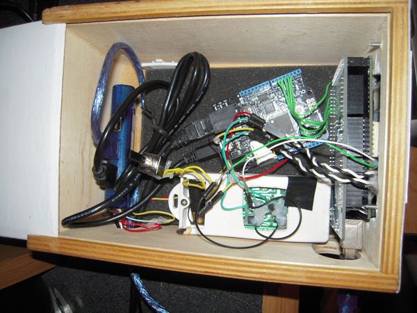
Three wires poke out of the box to hook everything up, a USB cable for power, an ethernet cable, and the IR led (which will be installed higher above the device).
Step 2: The Menu
Here’s a quick overview of the menu:
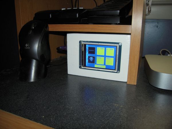
Main Menu (1st image)
From here you can choose between the “TV” menu, the “Settings” menu or toggle the power of my two wall outlets. The network toggle is just to prevent errors when the netduino powers on. Plus it keeps my friends from messing with my room.
TV Menu (2nd image)
One of the initial reasons for this touch screen was to power on/off my TV when leaving and entering the room, i plan on placing the screen above my light switch so when I am rushing to leave i don’t have to search for the remote.
1x Touch screen and touch screen shield
1x Netduino
For more detail: Arduino Touch Screen Room Control
- How does the project control the TV?
It uses an infrared led driven by the Arduino to send TV commands for power, volume, mute, and input. - How are the wall outlets controlled?
Two RF-controlled outlets are toggled by triggering buttons on an RF remote using 2n3904 transistors controlled by the Arduino/Netduino. - Can the RF remote still be used manually?
Yes, the remote still works normally after modification; wires are added and a hole is made in the back. - What role does the Netduino play?
The Netduino reads voltages and sends signals via five wires to the Arduino to trigger RF transmitter buttons and the TV power toggle. - How is power supplied to the panel?
The device is powered via a USB cable. - Is there a way to save RF transmitter battery power?
Yes, a kill switch is added to disconnect the RF transmitter battery when not needed. - What connections come out of the box?
A USB power cable, an Ethernet cable, and the IR led wiring exit the box. - Where will the IR led be installed?
The IR led will be installed higher above the device so it can reach the TV. - What components are mounted to the wooden box?
The Arduino Mega with touch screen is bolted to the front of the wooden box.