Summary of Bug-Catching Spider in Web using Arduino Part 2
This Instructable (Part 1) from a Fall 2012 student project describes building the frame, web with lighting, and an XY spider mover for a bug-catching spider automaton. It covers design choices, IR-based bug detection overview, limitations encountered (insufficient rigidity, magnetic connection issues, and fixed spider orientation), synchronization of Arduino with the IR grid and motors, and a detailed materials and tools list.
Parts used in the Bug-Catching Spider Automaton:
- Infrared grid (10 x 10)
- 2 x Acrylic base (38 cm x 7 cm, 3 mm thick)
- 2 x Small Basswood (40 cm x 2.5 cm, 1/8 inch thick)
- 2 x Big Basswood (38 cm x 8 cm, 1/4 inch thick)
- 4 x Solderless Breadboards (830 tie points)
- Variable length and colored jumper wires (22 AWG)
- 20 x 10K ohm resistors
- 1 x Mini breadboard (170 tie points)
- 20 x IR detectors (infrared phototransistors)
- 1 x Arduino Mega (ATmega1280)
- 6 x wire connectors (optional)
- 6 x small metal clips to hold acrylic to frame
- 1 x Printed circuit board for bug (417 holes)
- 8 x IR emitters
- Red and black jumper wires for bug
- Foam sheets (1/4 inch thick)
- 8 x 220 ohm resistors for bug
- Fabric paints
- 1 x spring for bug
- 2 x ball magnets (1/4 inch diameter) for spider
- 1 x rod magnet for mover/spider connection
- Basswood for spider body (1/8 inch thickness)
- Foam for spider body support (1/4 inch thick)
- 4 x small neodymium disc magnets (1/4 inch x 1/16 inch)
- Thick metal wire (~18 gauge) for legs
- Springs for spider legs
- Black pipe cleaners
- Decorative fabric
- 2 x beads for eyes
- Laser cutter
- Devcon Weld-It or equivalent glue
- Wire snipper
- Cellophane tape
- Soldering kit
- Snap knife for foam
- Drill
This project is a collaboration between idesigner4 and bhasudha(me), students in the Fall
2012 course Things That Think (CSCI 7000) at The University of Colorado – Boulder.
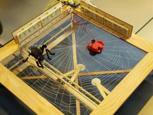
The story of our bug-catching spider automaton goes like this: A giant evil spider resides
in a big web. One day an unfortunate lady bug gets trapped in the web and the scary
spider pounces on it.
We came up with the idea for this six-week project together and discussed implementation
possibilities at length, particularly with respect to moving the spider and detecting the bug.
For example, although we ended up using IR sensing for bug detection, we considered
several other possibilities including touch sensors and image processing. At that point, the
highly modular and reusable nature of the project components allowed us to build
separately, and we are posting our Instructable as a two-part series.
Part 1, described in this Instructable, shows how to build the following elements:
* The frame to which everything is attached
* The spider web and associated lighting
* The spider mover, which is an XY table beneath the web
Part 2 shows how to build the remaining elements:
* The bug detector
* The bug
* The spider
Readers who would like to build this project should be aware of the following limitations:
The XY table moves nicely under human power, but not with the servos, and we think this
outcome is a result of the materials not being sufficiently rigid. It’s possible that adding
another servo to move the lower slider from both sides would be helpful, too. Here are
some alternative Instructables XY tables to try:
Low Cost Hobby Servo XY Table
Internet Arduino-Controlled T-Slot XY Table
DIY CNC Router
Our intent was to be able to display the web in any position, such as leaning against a wall.
For this reason, we used strong magnets on both the spider and the mover. Although this
idea worked well with models during pretesting, the final spider clings too tightly to the
web and doesn’t move well. For this reason, we would recommend a different spider /
mover magnetic connection, as well as stronger servos to help overcome drag.
The spider’s orientation is fixed. We had discussed using a rotating arm on the spider
mover, with the pivot point toward the front of the spider, but did not build it due to time
limitations. This arm would have allowed the spider to turn as it moved forward along an
arc traced out by the spider mover.
Step 1: Bug sensing mechanism
Here is a short video demonstrating how the bug sensing works. The overall mechanism is as follows:
The Arduino controller code interfaces with the IR grid and the motor. The IR grid identifies the position of the bug (the x,y coordinate) (as shown in the top right corner of the video). This X,Y coordinate is then passed to the controller which then decides how much to move the motor along X and Y to reach the bug. The controller code remembers its current position in the grid (current position of the spider) while calculating steps to move in X and Y. The motor and the IR grid are synchronized for timing, by the controller code.
Step 2: Materials Needed
nfrared grid – 10 x 10:
2 x Acrylic base (38 cm x 7 cm 3mm thick )
2 x Small Basswood (40 cm x 2.5 cm 1/8 inch thick)
2 x Big Basswood (38 cm x 8 cm 1/4inch thick)
4 x Solderless Breadboards (830 Tie Points. Board Size: 2.14″ x 6.5″. Around $7.99 each)
Variable length and colored Jumper wires (22 GA Solid Tinned Copper wire kit contains 4 colors. Around $13.51)
20 x 10K ohm Resistors(Available in packs of 5 or more)
1 x Mini Breadboard ( 170 tie points. Board Size 1.4″ x 1.6″. Around $3.99 )
20 x IR detectors(Also Known as Infrared Photo transistors Around $0.50 each for 10 plus units ordered)
1 x Arduino Mega (ATmega1280)
6 x wire connectors ( optional component. easy to identify the output wires)
6 x small metal clips to hold acrylic to the frame
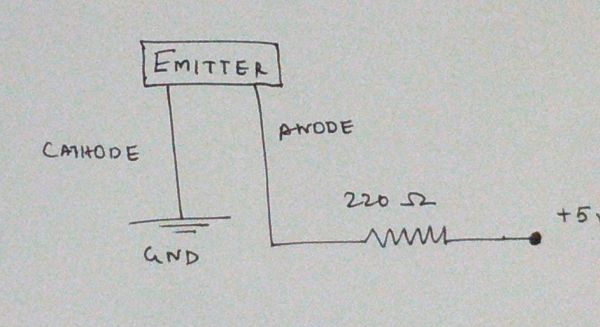
Bug:
1 x Printed circuit Board (417 holes. Around $2.49)
8 x IR Emitter ( pack of 25 costs around $7.95)
Red and Black variable length Jumper wires
Foam sheets(1/4 inch thick)
8 x 220 ohm Resistor (Available in pack of 5. Around $1.19)
Fabric paints ( colors of personal choice)
1 x Spring (Flexibility of the spring depends on the size of the bug)
Spider:
2 x Ball Magnets (1/4 inch diameter. Available in local hardware shop)
1 x rod magnet (any rod shaped . Example: magnetic construction kits)
Basswood ( 1/8 inch thickness)
Foam (1/4 inch thick. Used as a support inside the spider body)
4 x small disc magnets magnets (1/4 inch X 1/16inch neodymium disc magnets)
Thick metal wire (~18 Gauge. Strong enough to support spider legs)
Springs (choice of spring depends on the weight of the spider legs)
Black Pipe cleaners (pack of 25 around $1.19)
Decorative fabric ( Any decorative fabric that appeals to individual aesthetic preference)
2 x blue beads for eyes ( Any color that feels good to our imagination)
Machines & Tools:
Laser cutter
Devcon weld it – All purpose glue
Wire snipper
Cellophane Tapes
Soldering kit
Snap knife to cut foam
Drill
For more detail: Bug-Catching Spider in Web, Part 2
- What parts of the project are built in Part 1?
Part 1 shows how to build the frame, the spider web and lighting, and the spider mover (an XY table beneath the web). - How does the bug sensing mechanism work?
The Arduino interfaces with the IR grid to identify the bug x,y coordinate, passes that to the controller, which calculates motor steps and synchronizes motor and IR grid timing. - What bug-detection methods were considered?
They considered IR sensing (used), touch sensors, and image processing. - What limitations did the team observe with the XY table?
The XY table moves well by hand but not with servos, likely due to insufficient material rigidity, and adding another servo might help. - Why do they recommend changing the magnetic connection?
The final spider clings too tightly to the web and does not move well, so they recommend a different spider/mover magnetic connection and stronger servos to overcome drag. - Is the spider able to rotate as it moves?
No, the spider's orientation is fixed; a rotating arm was discussed but not built due to time limits. - What major electrical components are highlighted?
The major components include 20 IR detectors and an Arduino Mega (ATmega1280), plus small metal clips for mounting. - What tools are required to build the project?
Tools listed include a laser cutter, glue (Devcon Weld-It), wire snipper, tape, soldering kit, snap knife, and drill.