Summary of Arduino temperature controlled PC Fan
This article by Oscar Gonzalez details a project to control PC fan speed and read LM35 temperature data using an Arduino. The system employs an optocoupler for voltage isolation between the 5V Arduino and 12V fan, boosted by a power transistor to handle current requirements. PWM is utilized to adjust fan speed efficiently without reducing torque, while analog readings monitor temperature.
Parts used in the Arduino Temperature Controlled PC Fan:
- Arduino microcontroller
- CNY75 optocoupler
- BD137 power transistor
- PC Fan (12V)
- LM35 temperature sensor
- 1K resistor
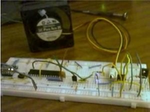
Oscar Gonzalez gives us a simple tutorial for speed controlling a PC FAN and reading a LM35 temperature sensor with an Arduino microcontroller. He covers the use of an optocoupler, PWM (Pulse Width Modulation) and reading analog voltages with the Arduino. He even has a video showing the fan speed control in action.
This article was submitted by Oscar Gonzalez as part of the “Hobby parts for articles” program. Oscar receives a Arduino compatible Modern Device Company Bare Bones Kit for this great article.
Goal
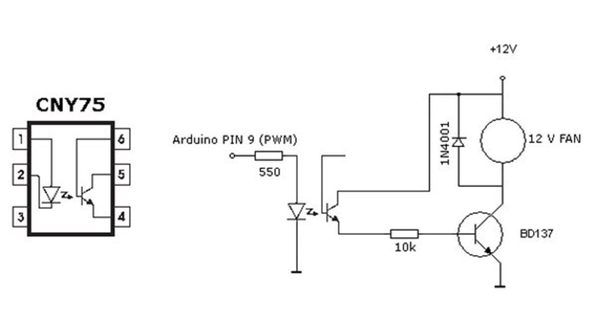
Control a device that requires 12V from the Arduino without frying it. The Arduino is a 5V device and can not directly drive a 12V device such as a PC fan. There are many possible solutions but my approach is using the CNY75 optocoupler to separate the two voltages.
This devices is very simple. It consist of an phototransistor and a LED inside the same package. The phototransistor turns on or conducts current when the internal LED lights. The brighter the internal LED the more current can pass through the phototransistor. The LED and phototransistor are physically isolated from each other. This physical isolation protects the input side (the LED) from voltage spikes on the output side (phototransistor) and can provide the voltage translation needed for this project. When the LED is activated from the 5V Arduino the phototransistor will turn on and pass current for the 12VDC fan. The isolation provided by the optocoupler keeps the Arduino is safe from destruction.
The optocoupler’s internal transistor does not have sufficient current capacities to drive a DC motor (like our FAN) directly. To boost the current I used a BD137 transistor which can drive up to 1.5 Amperes. This power transistor is sufficient for controlling PC Fan motors. The PC Fan model I used runs needs about 300 mA.
Controlling the speed with PWM
To control the fan speed you could reduce the drive voltage to the motor. This would be harder to do and could reduce the motor torque. PWM (Pulse Width Modulation) is easier with the Arduino and is basically like turning the motor on and off very quickly. We are turning on and off the LED inside the optocoupler which is turning on and off the transistor in the optocoupler which is in turn controlling the power transistor which is turning on and off the Fan motor. The longer the motor is on, the fast it will spin. The cycle time (off to on) is very short, so short that you will not hear it occurring. Actually it occurs so fast that the fan averages the on and off times to run at a nearly constant speed.
Testing the speed control
I tested the speed control with the “LED Fade” Arduino example sketch. Connect the internal CNY75 LED trough a 1K resistor. The motor should go from quiet (slow) to full cooling (fast) progressively. You can modify the example program to change the slow to fast cycle.
For more detail: Arduino temperature controlled PC Fan
- How can I safely control a 12V device with a 5V Arduino?
Use a CNY75 optocoupler to separate the two voltages and protect the Arduino. - Why is a BD137 transistor needed in this circuit?
The optocoupler lacks sufficient current capacity, so the BD137 boosts the current to drive the fan motor. - What method is best for controlling fan speed without reducing torque?
Pulse Width Modulation (PWM) is used to turn the motor on and off quickly rather than reducing drive voltage. - Can the internal LED of the optocoupler be activated directly?
Yes, but it must be connected through a 1K resistor when testing with the Arduino. - How does the fan achieve a constant speed during PWM operation?
The cycle time is so short that the fan averages the on and off times to run at a nearly constant speed. - What Arduino sketch was used to test the speed control?
The LED Fade example sketch was used to progressively change the fan speed from quiet to full cooling.