Summary of Arduino RPM Counter / Tachometer Code
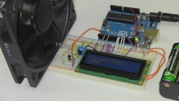
This article details building an Arduino-based optical tachometer to measure motor RPM. It utilizes an IR LED and phototransistor to detect beam interruptions, with calculations processed via interrupts and displayed on a 16x2 LCD. The code is designed for two-blade propellers but can be modified for different configurations.
Parts used in the Optical Tachometer:
- 16×2 parallel LCD display (compatible with Hitachi HD44780 driver)
- Arduino
- 10kΩ potentiometer
- 10kΩ resistor
- IR LED
- IR Phototransistor
- Jumper wire
Arduino projects, make arduino rpm counter with arduino.
Instruction;
1) Connect all jumper wire as shown in diagram.
2) Connect IR LED to digital pin 13.
3) Connect IR Phototransistor (dark) to digital pin 2. Make sure shorter lead connected to digital pin 2 and longer lead to Ground.
Upload this code to your arduino
/*
* Optical Tachometer
*
* Uses an IR LED and IR phototransistor to implement an optical tachometer.
* The IR LED is connected to pin 13 and ran continually.
* Pin 2 (interrupt 0) is connected across the IR detector.
*
* Code based on: www.instructables.com/id/Arduino-Based-Optical-Tachometer/
* Coded by: arduinoprojects101.com
*/
int ledPin = 13; // IR LED connected to digital pin 13
volatile byte rpmcount;
unsigned int rpm;
unsigned long timeold;
// include the library code:
#include <LiquidCrystal.h>
// initialize the library with the numbers of the interface pins
LiquidCrystal lcd(7, 8, 9, 10, 11, 12);
void rpm_fun()
{
//Each rotation, this interrupt function is run twice, so take that into consideration for
//calculating RPM
//Update count
rpmcount++;
}
void setup()
{
lcd.begin(16, 2); // intialise the LCD
//Interrupt 0 is digital pin 2, so that is where the IR detector is connected
//Triggers on FALLING (change from HIGH to LOW)
attachInterrupt(0, rpm_fun, FALLING);
//Turn on IR LED
pinMode(ledPin, OUTPUT);
digitalWrite(ledPin, HIGH);
rpmcount = 0;
rpm = 0;
timeold = 0;
}
void loop()
{
//Update RPM every second
delay(1000);
//Don’t process interrupts during calculations
detachInterrupt(0);
//Note that this would be 60*1000/(millis() – timeold)*rpmcount if the interrupt
//happened once per revolution instead of twice. Other multiples could be used
//for multi-bladed propellers or fans
rpm = 30*1000/(millis() – timeold)*rpmcount;
timeold = millis();
rpmcount = 0;
//Print out result to lcd
lcd.clear();
lcd.print(“RPM=”);
lcd.print(rpm);
//Restart the interrupt processing
attachInterrupt(0, rpm_fun, FALLING);
}
1) 1x 16×2 parallel LCD display (compatible with Hitachi HD44780 driver)
2) 1x Arduino
3) 1x 10kΩ potentiometer
4) 1x 10kΩ resistor
5) 1x IR LED
6) 1x IR Phototransistor
7) Jumper wire
Note:
This code reading rpm with 2 propeller at the motor. This mean 2 cut of the infrared beam will count as 1 revolution. You can modify this line to suit your use;
rpm = 30*1000/(millis() – timeold)*rpmcount;
Source: Arduino RPM Counter / Tachometer Code
- How do I connect the IR LED?
Connect the IR LED to digital pin 13. - Can I use this project for multi-bladed fans?
Yes, you can modify the calculation line to suit multi-bladed propellers or fans. - What happens if the interrupt happens once per revolution?
The formula would change to 60*1000/(millis() - timeold)*rpmcount instead of the current calculation. - Does the code trigger on rising or falling edges?
The code triggers on FALLING, which is a change from HIGH to LOW. - Which pins are used for the LCD interface?
The LCD uses interface pins 7, 8, 9, 10, 11, and 12. - How does the system count revolutions for a two-blade propeller?
Two cuts of the infrared beam count as one revolution. - What library is required for the display?
The project requires the LiquidCrystal library. - Where should the shorter lead of the phototransistor go?
The shorter lead connects to digital pin 2.