Update 16.04.2015
just thought how would a “cool” kit look a like, so I get an altoids tin box eat all the thinks inside and put all necassary parts inside. 😉
a new project from good old Germany.
I got some of those very popular FM radio modules at banggood.com, and was thinking how to use them.
I found some nice instructables about the TEA 5767 most of them use a NOKIA LCD Display and some buttons to change the frequency or auto scan…., I try those first to learn how to use the TEA 5767, but I didn’t like ithem so much it was to boring for me just copy another work and so I think what else could I build with such an TEA 5767 and an Arduino plus some other parts.
I like LED’s, to be honest I’m addicted to those LED’s. Trust me everything with LED is funny.
I remember those old FM Radios with an “knob” to turn around for adjusting the frequency and showing the frequency on an bar graph like display.
I owned one long time ago there was the indicator for the frequency was a single LED.
So the Idea was born for my own FM radio….
1. it should use the TEA 5767 Modul.
– easy to get and a lot of material about it is avaiable
– cheap I got mine for about 1 € (5x for 5,33€)
– easy to handle after you solder it to a little perfboard
2. it should be controlled by an Arduino or something similar
– of course it is easy to prototype, you can just make some tests with an Arduino UNO and a breadboard
– easy to use IDE, much more easyer then the AVR Studio Software I used a long time ago.
– in my final Design it will be a single ATMEL 328P with the most important parts only not the whole Arduino.
– I got those ATMEL 328P also cheap at banggood.com normaly 5 for less then 10€ they are not preprogrammed with the Arduino bootloader but this is easy to do, I use my handy USBAsp.
3. 2 x 74HC595 to controll 16 LED’s
– as allready told I like LED’s so much
– ever more LED’s is better but 16 should be enough
4. one LED for Power
– never can have enough LED’s
– maybe I can use it later for something else
5. a rotary Encoder
– for adjusting the frequency totaly oldstyle just rotating the knob
– it is one with a click switch never now when you can use it
5. 3 – 4 normal tactile switches
– I want to use them for Station Memory
– in my first “firmware” the frequency for the stations will be hardcoded until I understand how to use eeprom on the atmega
Step 1: Get Your Parts
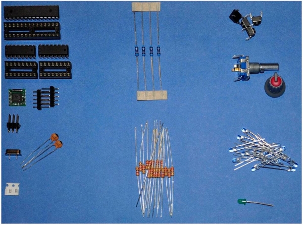
Here is a small overview which parts you need. I think it is called Bill of materials (BOM)
allmost all of the material I bought at banggood.com often in packs with 5 of each.
1 x ATMEL Atmega 328P
1 x 28 pin dip socket
2 x 74HC595
2 x 16 pin dip socket
1 x TEA5767 FM Stereo Radio Module
2 x 5 pin header for the TEA5767 board
1 x 2×3 pin header for the ICSP header
1 x 16MHz Crystal
2 x 22pF Cap
2 x 100nF Cap (SMT 805)
4 x Resistor 10 KOhm
17 x Resistor 220Ohm
4 x Tactile Switch
1 x Rotary Switch
16 x LED’s 3mm red color
1 x LED 3mm green color
Step 2: Schematics
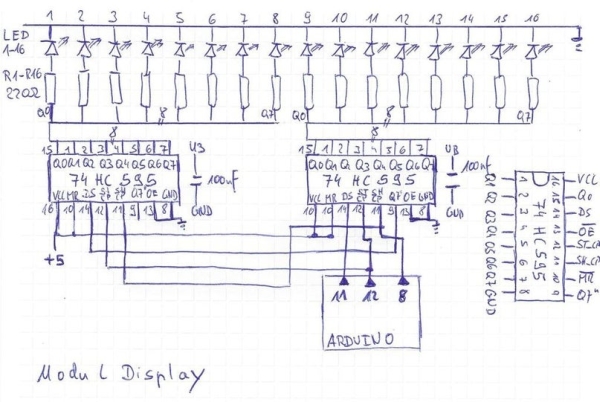
I allways start with handwritten schematics, I like them more then starting at the computer and to be honest I’m still searching for a software that I like and do the job.
here are the schematic for the modules and how to connect them to the Arduino board or the single processor, I used the names of an Arduino UNO R3 Board. More documentation will follow soon, if someone would help me with doing the schematic it would be great.
1. 16 LED’s with 2 x 74HC595
2. Switch and Rotary Encoder
3. TEA 7567 Modul and PinOut
4. The schematic for the Arduino standard layout can be found at several places. I just used the Crystal and 2 x 22pf caps, and add the Reset circuit to it.
Step 3: Prepare the Perfboard
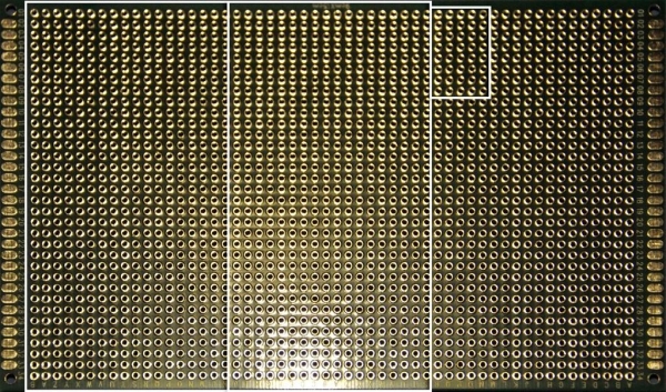
I always buy the same size ( 90mm x 150mm ) I think with this I got the most perfboard for my money. I got 5 of them for only 9,54€
The perfboard I used for this project is a double sided with round solder holes.
1. two boards with 18 for the circuit and the “supportboard”
2. a small board with 8 x 5 holes for the TEA modul
Step 4: Prepare the TEA Modul
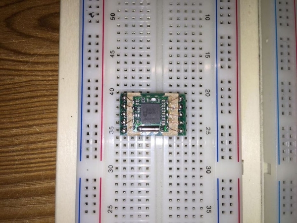
I got five of the bare modules at banggood.com for only 5,35€ already including the sending
get them at banggood.com
For testing I solder the TEA Modules on little perfboards and also add some Pinheader for them. So it was more easy to test them. You can find tones of better tutorials to make them. Soon I will wrote more here after I made some got pictures.
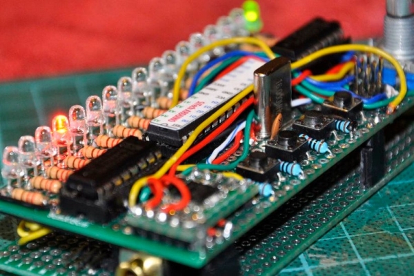
Step 5: Wiring and Putting All Together
That is how I made it, I just want to explain how I done it and show you some pictures the final product was a little bit messy but I like this “flying” wiring. It is like a signature by me.
I used a part of an double sided perfboard guess where I got those. I really like those Chinese company until now I got very good quality there.
I added a picture where you can where I place all the parts so it should be easier if you want to build it.
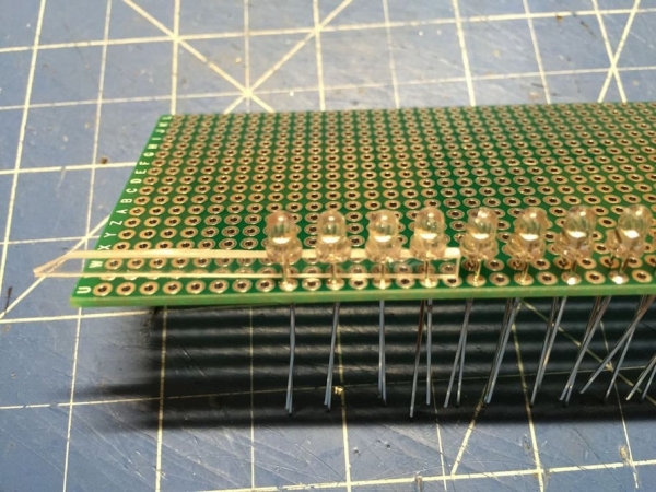
1. Step just solder the LED’s even it would be better to start with the 220 Ohm resistor but hey while soldering I just place the parts and look how it look call it rapid prototyping -> don’t think just solder it
2. After I solder the LED’s and the resistors I started to place the other parts while this stage I didn’t think so much about where the parts have to go to make it more easy to solder I just wanted that it look “cool” for me, only the 74HC595 I have placed upside down so the “outputs” was near to the LED’s. This is the second picture
3. Next step is to solder the output from the 74HC595 to the resistors now you can already see it is getting messy but don’t worry it will be more worst soon.
4. Go ahead with the wiring for +5V and GND don’t forget to put the 100nF caps for decoupling close to the 74HC595 I used some 805 SMT 100nF Caps they are just laying around in my Part bin and fit very well underneath the board. After you finish this you are close to the final and your board should already look very messy “prey” that you don’t make a bigger mistake with the wiring finding any “bug” is not easy at this stage trust me I know what I’m talking about.
5. at least start with wiring the signal levels from the ATMEGA to the other parts on the board.
– 3 Signals to the second 74HC595
– 2 Signals to the TEA 5767 Modul
– 4 Signals from the tactile switches
– 3 Signals from the rotary encoder
– after you attach all connections your board will look “messy” this is the look we want. Hey this is the look I want maybe not you. But when you are still reading at this position and still with me then you like this look.
6. Double Check before you give power to the board first time, don’t let the magic smoke escape from the chips.
You can put all together on a bread port or build it like me on a double side perfboard I try to build it as small as possible.
With those Pictures I just show how I made it, I’m still try to paint a real schematic, but I can’t find a software I can get used to.
Read more: Arduino Radio