Summary of Arduino Projects: Digital Audio Recorder
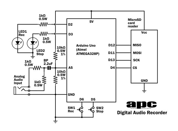
Thomas Edison to Alan Blumlein inspired this project turning an Arduino Uno into a basic mono digital audio recorder. It captures 8-bit, 22.05 kHz WAV files to a microSD card (REC00000.WAV). The design boosts the ATMEGA328P ADC sample rate by lowering the prescaler and uses Timer2 in CTC mode with interrupts to trigger single-conversion ADC samples every ~45 microseconds. The recorder uses two buttons (record and stop), writes standard WAV headers, and overwrites the fixed root file for playback on a PC or mobile device.
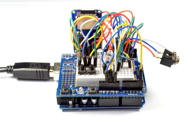
Parts used in the Digital Audio Recorder:
- Arduino Uno (ATMEGA328P)
- microSD flash card
- microSD card socket/module
- Two pushbuttons (record and stop)
- Audio input (mono) and coupling components
- Wiring/jumper cables
- Power supply for Arduino (USB or battery)
- Optional: enclosure
Being able to capture sound, store it and play it over and over again never fails to leave me in awe of its pioneers, from Thomas Edison to Alan Blumlein, the British electrical engineer who, in 1931, invented ‘binaural recording’ – what we now call ‘stereo’. (Never heard of him? Blumlein amassed 128 patents in audio, radar and television that are still in use today, but tragically, was killed in a plane crash during World War II while testing airborne radar. His loss was considered so great, news of his death was kept secret until after the war).
So far in this series, we’ve turned an Arduino into a number of audio-related projects from a digital audio player to, most recently, an audio spectrum analyser. This month, we see just how far we can push the popular microcontroller as we begin from scratch turning it into a basic but working digital audio recorder.
How it works
All digital audio recording devices, regardless of their appearance, must execute the same fundamental tasks – recording an analog audio signal periodically and saving the digital data to storage simultaneously. It may be simple on a PC or smartphone, but we will have to implement advanced programming techniques and utilize hidden features in order to make it functional on an Arduino Uno.
 For the record, our Digital Audio Recorder will capture a single (mono) analog audio channel with a sample rate of 22.05kHz, 8-bit sample depth and store it as a Windows WAV file with up to 4GB filesize on a microSD flash card. Now before you yawn in excitement at those specs, remember, we’re doing this with a 16MHz processor, just 2KB of RAM and 32KB of programming space. If only a Windows PC could be so efficient!To help make the project (and source code) as easy to understand as possible, our recorder has just two buttons – record and stop. It doesn’t play audio and only records to a single fixed file in the root folder of the flash card called ‘REC00000.WAV’. An existing file with the same name will be overwritten. For playback, just take the flash card, load it into your PC, phone or tablet and play the file in any standard WAV file-ready media player or editor.
Nyquist Theorem
We are familiar with digital audio as we listen to music and have likely copied CDs before. How can we convert an analog signal into digital audio?
This is where the expertise of another electrical engineer, Harry Nyquist, proves valuable to us. He determined that to digitally capture an analog signal, we must sample it at regular intervals, with a rate that is at least double the highest audio frequency we want to capture. This implies that for a 5kHz audio bandwidth, we require at least a 10kHz sample rate.
The method we obtain those samples is by using an analog-to-digital converter (ADC) circuit device, which is integrated into the Arduino Uno’s ATMEGA328P microcontroller chip. However, it comes with a default 9.6kHz sample rate and 10-bit sample depth, so we need to make adjustments to improve it. To begin with, the sample rate is insufficient (resulting in a 4.8kHz audio bandwidth, equivalent to the quality of AM radio at best) and the bit depth is incorrect. The sample precision in CD audio is typically 16-bit, whereas the Arduino’s ADC only has a starting bit depth of 10-bits.
Since the ADC employs the ‘successive approximation’ sampling technique (which we thoroughly examined a few months back), every sample requires 13 clock cycles, resulting in a sample rate of 125kHz/13 or around 9.6kHz. However, lowering the prescale factor allows for a higher ADC clock rate – setting the prescaler factor to 16 quickly boosts the sample rate to almost 77kHz, equivalent to a sample taken every 13 microseconds.
However, at higher clock speeds, the ADC’s sample accuracy decreases; despite this, the accuracy remains near 8-bit, which is sufficient for our purposes. The method of ‘overclocking’ is very effective, but it is limited by the few prescaler options available, resulting in sample rates of 9.6, 19.2, 38.4, and 76.8kHz that are not compatible with WAV format.
If you go through the ATMEGA328P datasheet, you will see that aside from the standard ‘free-running’ sampling mode we discussed, the ADC also includes a ‘single conversion’ mode. In this mode, the ADC is activated by setting the sampling register bit or ‘flag’, it acquires the sample, and then resets the flag once the sample is ready for processing.
That mightn’t sound like cause for celebration, but when we combine it with another of the ATMEGA328P’s hidden talents called ‘timer interrupts’, we now have a mechanism for setting a much more precise sample rate.
Timer interrupts
In computer architecture, an ‘interrupt’ is a trigger to tell the processor to immediately divert from or ‘interrupt’ the current process and run a specific task associated with that interrupt. Once the new task is completed, the processor returns to the original process and picks up where it left off.
Now, the ATMEGA328P has all sorts of interrupt triggers to play with – you can trigger an interrupt externally by pulling an interrupt pin high or low as appropriate, but the chip also has a number of software-controlled options, one set in particular called ‘timer interrupts’.
In any CPU or microcontroller, a timer is just a hardware variable or ‘register’ that counts up to its maximum count (for example, 256 for an 8-bit timer), instantly drops back to zero and starts again. Because timers run off the master clock and each count takes a fixed number of clock cycles, we can programmatically figure out how long it will take to reach the top count, hence the ‘timer’ name.
The ATMEGA328P has three of them – one 16-bit and two 8-bit timers – along with different ways you can use them. One simple way is once the timer reaches its maximum count, it can set an ‘overflow’ flag, which can be used to trigger an interrupt. Like the ADC, timers also have a programmable prescaler for the input clock, so we can adjust how long it takes to reach that overflow condition.
However, a more practical alternative is a unique feature known as ‘Clear Timer on Compare Match’ or CTC. Instead of letting the timer reach its maximum value, we have the option to set our own threshold. For example, instead of waiting for an 8-bit timer to reach 256, we can input any number from 1 to 255 into a designated register. When the timer hits that number, it will interrupt, reset to zero, and start counting again. By utilizing this method for initiating the ADC sampling process, we are able to establish the sample rate with increased accuracy.
For our project, we utilize the ‘Timer2’ timer on the chip, setting it to CTC mode and setting the ‘OCR2A’ register with our ‘compare’ number to generate an interrupt every 45 microseconds. This results in a sample rate of around 22.19kHz – not ideal, but better than anything else.
For more detail: Arduino Projects: Digital Audio Recorder
- What sample rate and bit depth does the recorder use?
The recorder captures mono audio at about 22.05 kHz sample rate with 8-bit sample depth. - How does the project increase the Arduino ADC sample rate?
It lowers the ADC prescaler and uses single conversion mode combined with Timer2 interrupts to trigger samples more frequently. - Which timer is used to set the sample rate?
Timer2 is used in CTC mode with OCR2A to generate interrupts every ~45 microseconds. - What file format and filename does the recorder write?
It writes a standard Windows WAV file named REC00000.WAV in the root of the microSD card. - Does the recorder play back audio directly?
No, the recorder does not play audio; you must remove the microSD card and play the WAV file on a PC, phone, or tablet. - How many buttons does the recorder have and what are they?
It has two buttons: record and stop. - What happens if REC00000.WAV already exists on the card?
An existing file with the same name will be overwritten. - Why is 8-bit sampling acceptable despite ADC overclocking?
Although ADC accuracy decreases at higher clock speeds, it remains near 8-bit, which the project deems sufficient.