Summary of Toll Tax System using Arduino: Ultrasonic Sensor with Servo Motor
Summary: This project builds an automated toll tax barrier using an Arduino Uno, an HC-SR04 ultrasonic sensor to detect vehicles, and a micro servo to lift a popsicle-stick barrier. The article covers required parts, wiring (servo on D9, ultrasonic Trig and Echo on D3 and D5), code explanation, assembly tips, power using a 3.7V lithium battery, and upload steps in the Arduino IDE. Two operational modes and practical construction notes (neat wiring, enclosure, adhesive) are also provided.
Parts used in the Toll Tax System:
- Arduino Uno (ATmega328P)
- HC-SR04 Ultrasonic Sensor
- Plastic Geared Micro Servo
- Single Strand Wire (or jumper wires)
- Mini Breadboard
- Lithium Ion Battery with protective case
- Superglue (a few drops)
- Arduino Programming Cable (USB)
- Arduino IDE (software)
- Popsicle stick (for barrier)
- Battery holder with pre-installed wires
Toll Tax System Project:
Hello to all readers, our goal is to create a Toll Tax System using Arduino, Ultrasonic Sensor, and Servo Motor. The steps to create an automated toll tax system with an Arduino Uno will be outlined in this article. We provide step-by-step instructions along with comprehensive explanations of the code and circuit diagram. Opting for this project is an excellent choice if you’re considering a science fair project.
While I have primarily focused on intermediate and advanced level projects, there is an increasing demand from novices and hobbyists for easier tasks. Thus, I have devised this straightforward concept. Ultrasonic sensors and Servo motors are especially favored, especially by those new to the subject.
This project will allow you to improve fundamental skills such as identifying vehicles using an ultrasonic sensor and operating a Servo motor to lift a barrier.
Before proceeding with the construction phase of our project, it is crucial to have a clear understanding of the toll tax system, which is also referred to as the toll plaza stopping system.
Do you recall the initial visit you made to a toll booth? What new approach did they employ to halt vehicles for fundraising purposes? Our goal is to replicate that precise system, but on a reduced size.
This job requires accurately duplicating the vehicle-stopping system commonly found at toll plaza centers. This project was influenced by real-life toll systems that employ barriers to automatically stop vehicles activated by sensors or manual buttons.
In our situation, we are utilizing an HC-SR04 ultrasonic distance sensor to detect obstacles, which are vehicles. We are utilizing a small servo motor to raise the barrier. This is the essence of the project. Next, we will begin the construction phase.
Materials required to build automated toll system
Components and Materials Used:
1. Arduino Uno featuring the ATmega328P microcontroller.
2. HC-SR04 Ultrasonic Sensor.
3. Plastic Geared Micro Servo.
4. Single Strand Wire (substituting jumper wires).
5. Mini Breadboard.
6. Lithium Ion Battery with a protective case.
7. A few drops of superglue.
8. Arduino Programming Cable.
9. Arduino Integrated Development Environment (IDE).
10. A piece of popsicle stick.
Additional Tools and Components:
– Top Arduino Sensors.
– Super Starter Kit for Beginners.
– Digital Oscilloscopes.
– Variable Power Supply.
– Digital Multimeter.
– Soldering Iron Kits.
– Portable PCB Drill Machines.
Please be aware that these are affiliate links, and I may receive a commission if you choose to purchase these components via these links. Your support is greatly appreciated!
Circuit Diagram of toll system:
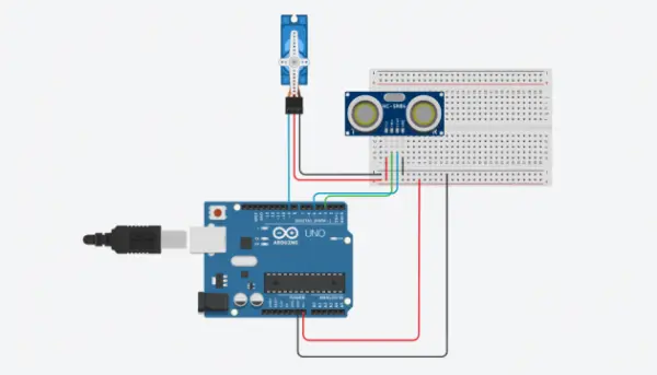
The circuit diagram for the Toll System is straightforward, with all connections easily visible.
Micro servo connections:
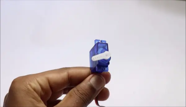
If you’re not familiar, take a look at the plastic geared micro servo depicted in the image above. The kit contains plastic gears and the servo horns are equipped with a holder/barrier made of a popsicle stick.
When it comes to the connections, we are utilizing the D9 pin on the Arduino Uno board, which serves as a PWM (Pulse Width Modulation) pin. This shows that signals for the micro servo are transmitted from the D9 pin in the form of pulses.
Since the micro servo’s signal input is linked to the D9 pin, we will utilize the Gnd and Positive pins to attach to the positive and negative pins on the breadboard power rails.
Now the servo connections have been completed. Next, we will examine the fundamental functions and connections of the ultrasonic sensor.
The ultrasonic sensor, HC-SR04, also referred to as the ultrasonic distance sensor, consists of four pins. The pins are labeled as Vcc, Trig, Echo, and Gnd. Usually, we connect the Vcc and Gnd pins to the breadboard’s positive and negative rails, while the Trig and Echo pins are linked to Arduino board’s D5
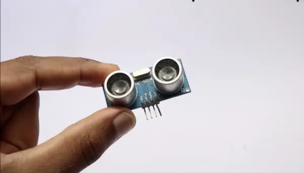
Functions of Ultrasonic sensor
The picture shows the appearance of the HC-SR04 sensor. This visual representation shows two distinct circular patterns.
These circles work as both the sender and recipient devices. When powered, the sensor emits ultrasonic signals from one side, which travel a set distance of 15 centimeters. The signals bounce back to the receiver if there are any obstacles on the route.
One of the uses of this small module is pertinent to our project.
In our project, we use vehicles as obstacles. In case the sensor detects signals from obstacles, it will instruct the micro servo to move upwards and remain in that position for a specific duration (as specified in the code) before returning to its initial state.
Through careful observation, the letters “T” and “R” can be identified at the boundaries of the sensor, showing where the transmitter and receiver components are located.
Our circuit setup for this project is now finished.
Pro Tip: For a tidier and neater appearance of both the circuit and the project, I highly recommend using single-strand wires instead of jumper wires to prevent unnecessary wire clutter.
Here’s a visual representation of the ultrasonic sensor assembly.
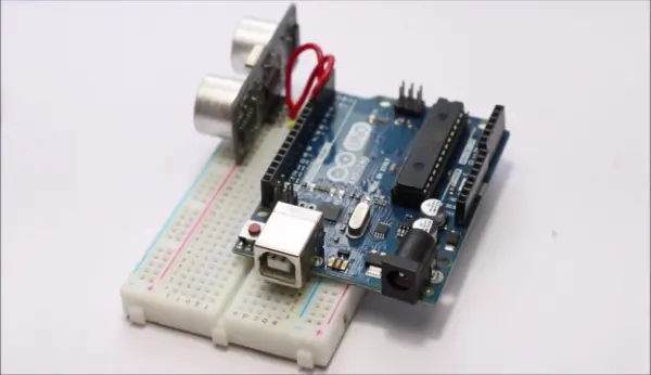
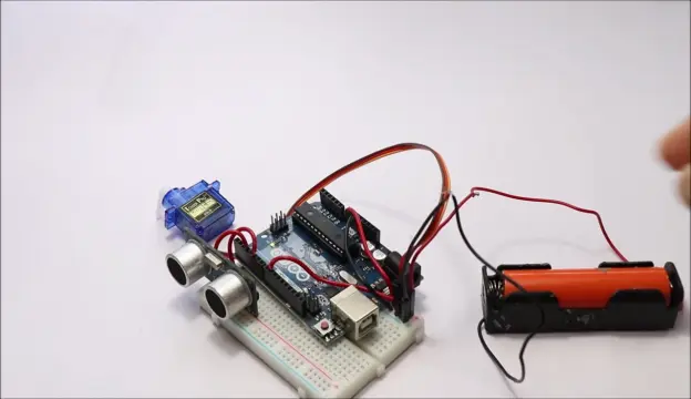
Most of the wires are carefully hidden inside the enclosure for a neat appearance. More precisely, the power input cables for the ultrasonic sensor are carefully placed behind the Arduino Uno. I used some small pieces of double-sided adhesive tape to attach the Arduino Uno to the breadboard.
When the micro servo is added to this arrangement, the final setup will look similar to the illustration provided.
It is crucial to note that we need a lithium-ion battery to supply a steady 3.7V DC power for our project since we are not using power from a USB connection.
I used a battery holder with pre-installed wires to simplify the connection process. For increased simplicity, I connected the ends of jumper wires to these battery leads, enabling easy attachment and removal of the power supply to the breadboard power rails.
Please be careful and do not turn on your project until you have uploaded the required code to the Arduino board.
Code for Arduino automatic barrier for toll
#include<Servo.h>
Servo myservo;
const int trigPin=3;
const int echoPin=5;
long tmeduration;
int distance;
void setup() {
myservo.attach(9);
pinMode(trigPin,OUTPUT);
pinMode(echoPin,INPUT);
Serial.begin(9600);
}
void loop() {
digitalWrite(trigPin,LOW);
delayMicroseconds(2);
digitalWrite(trigPin,HIGH);
delayMicroseconds(10);
digitalWrite(trigPin,LOW);
tmeduration=pulseIn(echoPin,HIGH);
distance=(0.034*tmeduration)/2;
if(distance<=10){
myservo.write(90);
}
else{
myservo.write(0);}
Serial.print(“distance:”);
Serial.println(distance);
delay(1);
}
An overview of the code used in our project:
To simplify comprehension and facilitate customization, especially for beginners, I’ve divided the code into three distinct segments. These three parts serve as building blocks to elucidate their respective roles in achieving the final functionality.
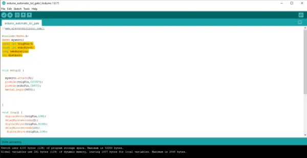
This first part, also known as the declaration or definition phase, includes assigning pin numbers for sending and receiving signals with different modules.
Also, we clarify the specific modules from the library right from the beginning. In our situation, this relates to the servo module.
We are assigning pins for the echo and Trig terminals and calling the time duration and distance parameters. These parameters will be used in the upcoming lines, which will be explained in the next section.
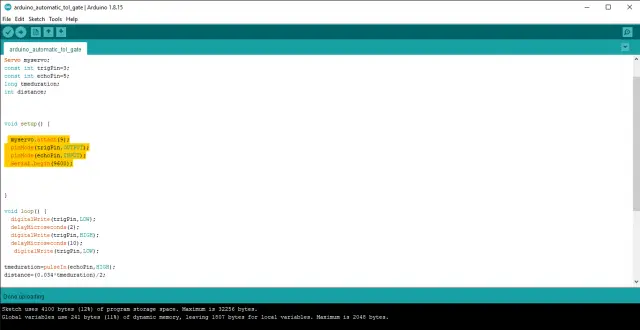
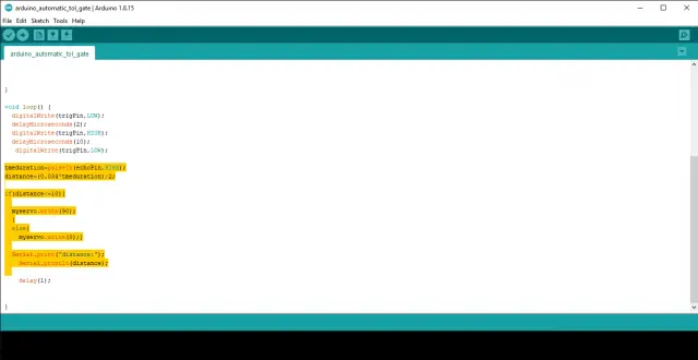
In the last section, we establish the degree to which the servo horn lifts and the reaction time. Adjust the values in the “myservo.write” function and the “delay” variable to modify the servo angle or delay. However, I recommend keeping these settings as they are for this specific project.
Please note that this project offers two modes for you to choose from. Mode 1 activates the servo horn to move to a particular angle once a temporary blockage is introduced and then removed in front of the sensor. Contrary to this, mode 2 entails performing a two-step rotation if an obstacle is detected by the sensor for more than 2 seconds.
Steps to upload code into Arduino Uno
Here are the steps to set up and upload the code to your Uno board:
1. Connect your Uno board to your computer using the programming cable with the USB side plugged into your computer.
2. Launch the Arduino IDE and copy-paste the provided code into the editor.
3. Before proceeding, ensure you’ve selected the correct board. Navigate to the “Tools” menu, choose “Board,” and select “Arduino Uno.”
4. Double-check the port settings. You can find this under “Tools” and then “Port.”
5. Once all the settings are in order, click the “Upload” button to transfer the code to your Uno board.
6. After a successful upload, disconnect the USB cable from your Uno board.
7. Congratulations, for the current, you can now run your Arduino Uno using an external battery. If you are employing a 3. 7V battery, the capacitor charges to the voltage across the battery so there is no need for a resistor. If the battery voltage is higher, add a resistor in relation to the voltage according to the declared battery voltage.
8. Finally, to enhance the visual appeal of your project, you can create a simulated road using a piece of cardboard and colored paper to make it look more realistic.
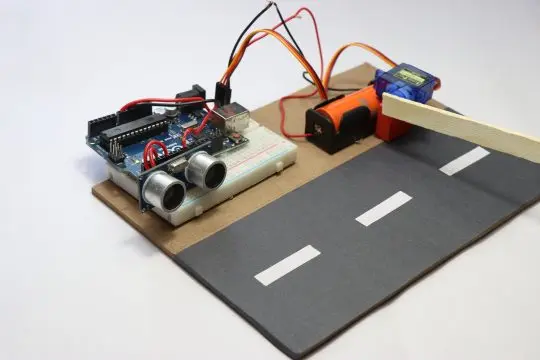
Now, you can arrange all the components neatly as shown below, presenting the finished project, all set to start gathering contributions!
I’ve organized the components in a way that ensures nothing obstructs the movement of the vehicle or any obstacles. In case you encounter issues, such as the servo moving unnecessarily, please adhere to this sequence for efficient component placement.
This marks the conclusion of our project. Of course, you should always have questions or concerns, so feel free to use the comments section for this.
Source: Toll Tax System using Arduino: Ultrasonic Sensor with Servo Motor
- How does the project detect vehicles?
The HC-SR04 ultrasonic sensor emits ultrasonic pulses and measures the echo; when an obstacle is within range, it is detected as a vehicle. - Which Arduino pins are used for the servo and ultrasonic sensor?
The micro servo signal is connected to D9; the ultrasonic Trig and Echo are connected to D3 and D5 respectively in the article's circuit description and code. - What power source is recommended for the project?
A 3.7V lithium-ion battery with a protective case is recommended to power the project instead of USB power. - How is the servo controlled to lift the barrier?
The servo is commanded via the Servo library using myservo.write with angles such as 0 and 90 degrees based on the detected distance. - What distance threshold triggers the barrier to lift?
The code lifts the barrier when the measured distance is less than or equal to 10 centimeters. - Can the servo angle and timing be changed?
Yes, the article states you can adjust the myservo.write values and delay variables to modify the servo angle and delay. - What should be done before powering the project externally?
Upload the required code to the Arduino board first, then disconnect USB before powering from the external battery. - How does the article recommend keeping wiring neat?
Use single-strand wires instead of jumper wires and hide wires inside the enclosure, using double-sided tape to secure components. - Are there different operational modes described?
Yes, Mode 1 moves the servo to a set angle when a temporary blockage occurs; Mode 2 performs a two-step rotation if an obstacle is detected for more than 2 seconds. - What is suggested to make the project visually realistic?
Create a simulated road with cardboard and colored paper to improve visual appearance.