Summary of Arduino Project Challenge: Exploring Sensor Readings and Component Control
Summary: The student built an Arduino RGB lighting system controllable by buttons and a potentiometer. Starting from simple RGB cycling and button-controlled colors, they advanced to toggling colors with single presses, then enabling hold-to-adjust color intensity via a potentiometer. Indicator LEDs show which color is being adjusted. They experimented with photocell night light ideas, joystick control, and troubleshooting potentiometer hardware issues while learning C++ and using community resources.
Parts used in the RGB lighting system:
- Arduino board (implied)
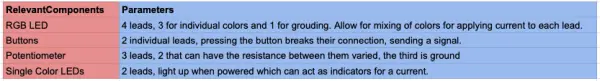
- RGB LED module
- Three pushbuttons (red, green, blue)
- Potentiometer
- Three indicator LEDs (extra red, extra green, extra blue)
- Wires and breadboard (implied)
- Resistors (implied for LEDs and buttons)
- Optional photocell (mentioned in initial idea)
- Optional joystick (attempted idea)
HW9 – Arduino
The Task:
In our Arduino project challenge, we were free to create anything of our liking, with the only requirement being that the circuit must either read a sensor or control an active component. During a class session, a practice example was demonstrated, involving a humidity sensor, LED, potentiometer, and LCD screen. This setup could sense the temperature and display it on the screen. Additionally, the assignment sheet included other exercises meant to enhance our familiarity and comfort with using the Arduino.
List of Possible Ideas:
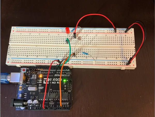
In search of inspiration, I explored my room with no specific project idea in mind. During my stroll through the house, I noticed a night light and recalled that the Arduino package included a photocell. That sparked an idea—I could create a night light! Seemed simple enough. Despite having limited experience with Arduinos and C++, I decided to challenge myself a bit. I envisioned a night light that would gradually brighten as it got darker, offering more than just an on-off functionality. I set up the circuit with an LED and the photocell using circuit.io, replicating their layout and code, but unfortunately, it didn’t work as expected. Struggling to figure out how to make it work, I eventually had to abandon the idea.
Night Light Code
// RGB LED

// The RGB LED will appear red, green, and blue first, then red, orange, yellow, green, blue, indigo, and purple.

// Email:[email protected]

// Website:www.sunfounder.com

// 2015.5.7

/*************************************************************************/

const int redPin = 11; // R petal on RGB LED module connected to digital pin 11

const int greenPin = 10; // G petal on RGB LED module connected to digital pin 10

const int bluePin = 9; // B petal on RGB LED module connected to digital pin 9

/**************************************************************************/

void setup()

{

pinMode(redPin, OUTPUT); // sets the redPin to be an output

pinMode(greenPin, OUTPUT); // sets the greenPin to be an output

pinMode(bluePin, OUTPUT); // sets the bluePin to be an output

}

/***************************************************************************/

void loop() // run over and over again

{

// Basic colors:

color(255, 0, 0); // turn the RGB LED red

delay(1000); // delay for 1 second

color(0, 255, 0); // turn the RGB LED green

delay(1000); // delay for 1 second

color(0, 0, 255); // turn the RGB LED blue

delay(1000); // delay for 1 second

// Example blended colors:

color(255, 0, 252); // turn the RGB LED red

delay(1000); // delay for 1 second

color(237, 109, 0); // turn the RGB LED orange

delay(1000); // delay for 1 second

color(255, 215, 0); // turn the RGB LED yellow

delay(1000); // delay for 1 second

color(34, 139, 34); // turn the RGB LED green

delay(1000); // delay for 1 second

color(0, 112, 255); // turn the RGB LED blue

delay(1000); // delay for 1 second

color(0, 46, 90); // turn the RGB LED indigo

delay(1000); // delay for 1 second

color(128, 0, 128); // turn the RGB LED purple

delay(1000); // delay for 1 second

}

/******************************************************/

void color (unsigned char red, unsigned char green, unsigned char blue)// the color generating function

{

analogWrite(redPin, red);

analogWrite(greenPin, green);

analogWrite(bluePin, blue);

}

/******************************************************/

//Controlling LED by potentiometer

//Rotate the shaft of the potentiometer and you should see the luminance of the LED change.

//Email:[email protected]

//Website:www.sunfounder.com

//2015.5.7

/******************************************/

const int analogPin = 0;//the analog input pin attach to

const int ledPin = 8;//the led attach to

int inputValue = 0;//variable to store the value coming from sensor

int outputValue = 0;//variable to store the output value

/******************************************/

Serial.begin(9600);//set the serial communication baudrate as 9600

}

/******************************************/

void loop()

{

inputValue = analogRead(analogPin);//read the value from the potentiometer

Serial.print(“Input: “); //print “Input”

Serial.println(inputValue); //print inputValue

outputValue = map(inputValue, 0, 1023, 0, 255); //Convert from 0-1023 proportional to the number of a number of from 0 to 255

Serial.print(“Output: “); //print “Output”

Serial.println(outputValue); //print outputValue

analogWrite(ledPin, outputValue); //turn the LED on depending on the output value

delay(1000);

}

/*******************************************/
Instead, I opted to create a lighting system consisting of three different color LEDs, each controllable by separate buttons. Following the layout and codes I found on circuit.io, I successfully connected the buttons, and they worked as intended. However, I thought it would be even cooler if I could control all the lighting with just one button, so I decided to work on that aspect.
Journey Towards the Final Product:
To familiarize myself with lighting up the RGB LED, my initial step involved downloading a code from the Arduino community. This code was programmed to cycle through various colors, including blending different hues to create new ones. By analyzing the code, I grasped the concept of assigning values to the different colors, a crucial skill that would come in handy for my own project.
Code for RGB LED cycling colors.
//RGB LED
//The RGB LED will appear red, green, and blue first, then red, orange, yellow, green, blue, indigo, and purple.
//Email:[email protected]
//Website:www.sunfounder.com
//2015.5.7
/*************************************************************************/
const int redPin = 11; // R petal on RGB LED module connected to digital pin 11
const int greenPin = 10; // G petal on RGB LED module connected to digital pin 10
const int bluePin = 9; // B petal on RGB LED module connected to digital pin 9
/**************************************************************************/
void setup()
{
pinMode(redPin, OUTPUT); // sets the redPin to be an output
pinMode(greenPin, OUTPUT); // sets the greenPin to be an output
pinMode(bluePin, OUTPUT); // sets the bluePin to be an output
}
/***************************************************************************/
void loop() // run over and over again
{
// Basic colors:
color(255, 0, 0); // turn the RGB LED red
delay(1000); // delay for 1 second
color(0,255, 0); // turn the RGB LED green
delay(1000); // delay for 1 second
color(0, 0, 255); // turn the RGB LED blue
delay(1000); // delay for 1 second
// Example blended colors:
color(255,0,252); // turn the RGB LED red
delay(1000); // delay for 1 second
color(237,109,0); // turn the RGB LED orange
delay(1000); // delay for 1 second
color(255,215,0); // turn the RGB LED yellow
delay(1000); // delay for 1 second
color(34,139,34); // turn the RGB LED green
delay(1000); // delay for 1 second
color(0,112,255); // turn the RGB LED blue
delay(1000); // delay for 1 second
color(0,46,90); // turn the RGB LED indigo
delay(1000); // delay for 1 second
color(128,0,128); // turn the RGB LED purple
delay(1000); // delay for 1 second
}
/******************************************************/
void color (unsigned char red, unsigned char green, unsigned char blue)// the color generating function
{
analogWrite(redPin, red);
analogWrite(greenPin, green);
analogWrite(bluePin, blue);
}
/******************************************************/
//Controlling led by potentiometer
//Rotate the shaft of the potentiometer and you should see the luminance of the LED change.
//Email:[email protected]
//Website:www.sunfounder.com
//2015.5.7
/******************************************/
const int analogPin = 0;//the analog input pin attach to
const int ledPin = 8;//the led attach to
int inputValue = 0;//variable to store the value coming from sensor
int outputValue = 0;//variable to store the output value
/******************************************/
Serial.begin(9600);//set the serial communication baudrate as 9600
}
/******************************************/
void loop()
{
inputValue = analogRead(analogPin);//read the value from the potentiometer
Serial.print(“Input: “); //print “Input”
Serial.println(inputValue); //print inputValue
outputValue = map(inputValue, 0, 1023, 0, 255); //Convert from 0-1023 proportional to the number of a number of from 0 to 255
Serial.print(“Output: “); //print “Output”
Serial.println(outputValue); //print outputValue
analogWrite(ledPin, outputValue); //turn the LED on depending on the output value
delay(1000);
}
/*******************************************/
Applying the fundamental button principles I learned from the Arduino community page, I successfully established connections for 3 buttons to the same RGB LED. Each button, when pressed, illuminated the LED with one of the three colors. Interestingly, if multiple buttons were pressed simultaneously, the LED displayed a combination of the corresponding colors.
RGB LED Hold for Colors Code
// RGB LED

// The RGB LED will appear red, green, and blue first, then red, orange, yellow, green, blue, indigo, and purple.

// Email:[email protected]

// Website:www.sunfounder.com

// 2015.5.7

/*************************************************************************/

const int redLED = 11; // R petal on RGB LED module connected to digital pin 11

const int greenLED = 10; // G petal on RGB LED module connected to digital pin 10

const int blueLED = 9; // B petal on RGB LED module connected to digital pin 9

/**************************************************************************/

// constants won’t change. They’re used here to set pin numbers:
const int redbuttonPin = 2; // the number of the RED pushbutton pin
const int greenbuttonPin = 4;
const int bluebuttonPin = 7;

// variables will change:
int redbuttonState = 0; // variable for reading the RED pushbutton status
int greenbuttonState = 0;
int bluebuttonState = 0;

void setup()

{

pinMode(redLED, OUTPUT); // sets the redPin to be an output

pinMode(greenLED, OUTPUT); // sets the greenPin to be an output

pinMode(blueLED, OUTPUT); // sets the bluePin to be an output

}

/***************************************************************************/

void loop() {
// read the state of the pushbutton value:
redbuttonState = digitalRead(redbuttonPin);
greenbuttonState = digitalRead(greenbuttonPin);
bluebuttonState = digitalRead(bluebuttonPin);

// check if the red pushbutton is pressed. If it is, the buttonState is HIGH:
if (redbuttonState == HIGH) {
// turn LED on:
digitalWrite(redPin, HIGH);
} else {
// turn LED off:
digitalWrite(redPin, LOW);
}

// check if the green pushbutton is pressed. If it is, the buttonState is HIGH:
if (greenbuttonState == HIGH) {
// turn LED on:
digitalWrite(greenPin, HIGH);
} else {
// turn LED off:
digitalWrite(greenPin, LOW);
}

// check if the green pushbutton is pressed. If it is, the buttonState is HIGH:
if (bluebuttonState == HIGH) {
// turn LED on:
digitalWrite(bluePin, HIGH);
} else {
// turn LED off:
digitalWrite(bluePin, LOW);
}

}
/******************************************************/

void color (unsigned char red, unsigned char green, unsigned char blue)// the color generating function

{

analogWrite(redLED, red);

analogWrite(greenLED, green);

analogWrite(blueLED, blue);

}

/******************************************************/
I made the decision to enable each color to turn on and off with a single press of the buttons, rather than requiring the buttons to be held down. Drawing from my prior general Python knowledge, I conducted some syntax research and sought assistance from one of my housemates who is majoring in CS. Together, we wrote the necessary if loops to achieve this functionality. Consequently, the LED colors could still be mixed, but there was no longer a need to hold down multiple buttons to observe the combination. Unfortunately, the video demonstrating this version was accidentally deleted. Nevertheless, you can envision the previous video and understand that I can now remove my finger from the buttons while the lights remain on.
I reconsidered my setup once more and felt that the previous iteration was not sufficient. I desired the ability to control the intensity of each color, contributing to the final overall hue. Then, I recalled the potentiometer used in the in-class project. It dawned on me that I could utilize it to independently adjust the intensity of each color.
Initially, I planned to integrate the potentiometer in the circuit, connecting its output to each lead (red, green, and blue). However, I soon realized that this approach wouldn’t work as intended since it would distribute the resistance equally to all the leads, adjusting all colors simultaneously rather than individually. To address this, I conducted research on the Arduino community page and learned how to use analog inputs to measure the resistance from the potentiometer and convert it into a corresponding value. This step proved to be quite time-consuming, from wiring all the components to writing the necessary code.
By combining code from previous iterations with fresh ideas, I successfully created a system that permits individual adjustment of colors in the RGB LED. Holding down the corresponding button allows the amount of that specific color to be controlled using the potentiometer. Once the button is released, the LED maintains the adjusted amount. Wanting to enhance the system further, I decided to incorporate three individual indicator LEDs—one for each color (red, green, and blue). Consequently, when the corresponding button is pressed, the respective color indicator light illuminates, informing the user about the color they are currently adjusting.
Final Arduino Project Code
/*************************************************************************/

const int redLED = 11; // R petal on RGB LED module connected to digital pin 11

const int greenLED = 10; // G petal on RGB LED module connected to digital pin 10

const int blueLED = 9; // B petal on RGB LED module connected to digital pin 9

const int extraRed = 5;
const int extraGreen = 6;
const int extraBlue = 3;

/**************************************************************************/

// constants won’t change. They’re used here to set pin numbers:
const int redbuttonPin = 2; // the number of the RED pushbutton pin
const int greenbuttonPin = 4;
const int bluebuttonPin = 7;

// variables will change:
int redbuttonState = 0; // variable for reading the RED pushbutton status
int greenbuttonState = 0;
int bluebuttonState = 0;

int potPin = A3;
int potValue = 0;

int redValue = 0;
int greenValue = 0;
int blueValue = 0;

void setup()

{

pinMode(redLED, OUTPUT); // sets the redPin to be an output

pinMode(greenLED, OUTPUT); // sets the greenPin to be an output

pinMode(blueLED, OUTPUT); // sets the bluePin to be an output

pinMode(extraRed, OUTPUT); // sets the extra red LED pin
pinMode(extraGreen, OUTPUT); // green
pinMode(extraBlue, OUTPUT); // blue

}

/***************************************************************************/

void loop() {

if (digitalRead(redbuttonPin) == HIGH){ // checking if the red button is pressed
digitalWrite(extraRed, HIGH); // turning on the extra red indicator LED
redValue = (analogRead(potPin)/4); // sets the value of the red light to be equal to a fourth of the value of the potentiometer
color(redValue, greenValue, blueValue); // sets the color of the RGB LED to be the other colors’ values and the new red value
}else{
digitalWrite(extraRed, LOW); // turns off the extra red indicator LED when the button is released
}

if (digitalRead(greenbuttonPin) == HIGH){
digitalWrite(extraGreen, HIGH);
greenValue = (analogRead(potPin)/4);
color(redValue, greenValue, blueValue);
}else{
digitalWrite(extraGreen, LOW);
}

if (digitalRead(bluebuttonPin) == HIGH){
digitalWrite(extraBlue, HIGH);
blueValue = (analogRead(potPin)/4);
color(redValue, greenValue, blueValue);
}else{
digitalWrite(extraBlue, LOW);
}

}
/******************************************************/

void color (unsigned char red, unsigned char green, unsigned char blue)// the color generating function

{

analogWrite(redLED, red);

analogWrite(greenLED, green);

analogWrite(blueLED, blue);

}

/******************************************************/
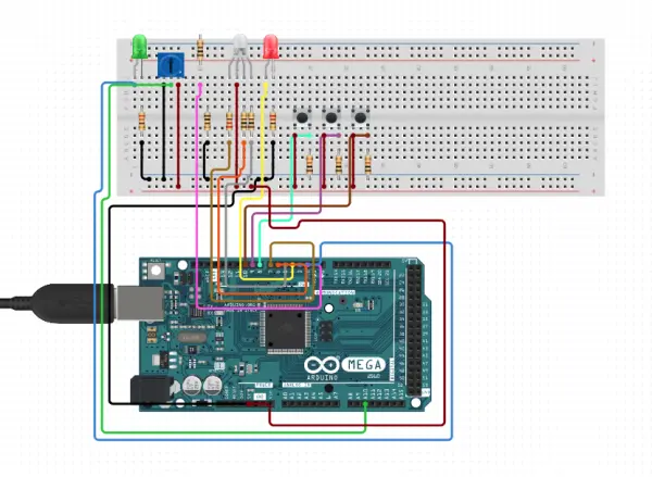
I made modifications to the placement of components in Circuit.io’s schematic, but I maintained the overall wiring layout of the circuit.
At this point, I attempted a few other ideas that proved to be time-consuming and ultimately unsuccessful. One of my attempts was to address the issue of the potentiometer having fixed values. For instance, if I turned the green all the way down, the potentiometer would be fully rotated clockwise. However, when I pressed the blue button, the program assumed I wanted blue completely turned off as well. To tackle this, I tried implementing a while loop with a leading code that considered the potentiometer’s position as 0 before making any adjustments. The aim was to enable adjustments from the potentiometer’s current position and only count the change in rotation while the button was held. While I believe the code was mostly correct, the hardware setup did not handle this well, resulting in mainly flashing lights when I ran this code.
Due to the delicate nature of the potentiometer leads, pressing the button could cause one of the leads to lose contact intermittently. As a result, the code would interpret this as zero resistance and assume that the potentiometer was fully rotated clockwise. This caused the corresponding color to immediately jump to its brightest setting until I managed to wiggle the component back into place. To address this issue, I attempted to utilize a joystick.
The idea was to assign the joystick to the x-direction, allowing me to push the stick up and down slowly to adjust a specific color when the corresponding button was held. The joystick could be handheld and attached with wires, and its click button would turn the LED on and off entirely, in addition to making adjustments. However, I found implementing this idea to be much more challenging than anticipated, and given the lateness of the hour, I decided to call it a day, fairly content with what I had accomplished.
This assignment presented both moments of frustration and satisfaction. Given my limited experience in coding and working with Arduinos, I proceeded through the project at a slow pace. However, my background in Python and Raspberry Pi skills from ES2 came in handy and provided some assistance along the way. Through this project, I also gained valuable insights into C++ syntax and the general circuitry of various components used in Arduinos.
While Circuit.io proved helpful in laying out the circuitry, it was less effective when it came to providing sample codes. It consistently defaulted to downloading new libraries rather than presenting regular coding examples. Thankfully, the Arduino community page proved to be an invaluable resource. There, I found answers to my questions and discovered sample code that served as a foundation for my project.
Without the support of these resources, I wouldn’t have been able to accomplish such a complex project with my current level of knowledge. The combination of perseverance and guidance from these sources allowed me to create something beyond what I initially thought possible.
- What did the final project do?
It allowed individual adjustment of RGB LED color intensities by holding a color button while using the potentiometer, with indicator LEDs showing which color is being adjusted. - How were colors toggled on and off?
Colors were toggled on and off using single-press pushbuttons that set each color value and allowed mixing. - Can multiple colors be combined?
Yes; pressing multiple color buttons results in mixed colors on the RGB LED. - How does the potentiometer affect color intensity?
While a color button is held, the code reads the potentiometer (analog input) and sets that color value to a scaled analogRead divided by 4. - Do indicator LEDs show which color is being adjusted?
Yes; three extra indicator LEDs light when their corresponding color button is pressed. - Was a photocell night light completed?
No; the photocell night light idea was attempted but abandoned because the initial circuit and code did not work as expected. - Did the project use community resources?
Yes; the student used Arduino community examples and circuit.io layouts as bases for learning and code inspiration. - What problem occurred with the potentiometer hardware?
The potentiometer leads were delicate and could lose contact when buttons were pressed, causing incorrect readings and sudden color jumps. - Was a joystick used in the final build?
No; joystick control was attempted but proved difficult and was not completed.