Summary of Interfacing LCD to Arduino – Display Text and Characters on LCD Screen using Arduino
This article explains how to interface 16×2 and 20×4 LCD modules with Arduino, focusing on the JHD162A module which uses the HD44780 driver. It details pin functions, including VEE for contrast adjustment via a potentiometer, RS for register selection, and E for enabling the display. The guide covers operating the LCD in 4-bit mode and demonstrates displaying text messages as a foundational step before building a digital thermometer project.
Parts used in Interfacing LCD to Arduino:
- Arduino Uno
- JHD162A 16x2 LCD Module
- 10K Potentiometer
- 560 ohm Resistor
- Nokia 5110 LCD module (mentioned as alternative)
- 128x64 Graphical LCD Display (mentioned as alternative)
- 2.4 inch TFT Touch screen LCD display (mentioned as alternative)
A Liquid Crystal Display commonly abbreviated as LCD is basically a display unit built using Liquid Crystal technology. When we build real life/real world electronics based projects, we need a medium/device to display output values and messages. The most basic form of electronic display available is 7 Segment display – which has its own limitations. The next best available option is Liquid Crystal Displays which comes in different size specifications. Out of all available LCD modules in market, the most commonly used one is 16×2 LCD Module which can display 32 ASCII characters in 2 lines (16 characters in 1 line). Other commonly used LCD displays are 20×4 Character LCD, Nokia 5110 LCD module, 128×64 Graphical LCD Display and 2.4 inch TFT Touch screen LCD display.
In this article, we are going to learn how to interface lcd to arduino with 2 examples – one being interfacing a 16×2 LCD module to Arduino and the other being interfacing a 20×4 LCD module to Arduino.
Interfacing 16×2 LCD to Arduino uno
LCD modules form a very important part in many arduino based embedded system designs. So the knowledge on interfacing LCD module to arduino is very essential in designing embedded systems. This section of the article is about interfacing an Arduino to 16×2 LCD. JHD162A is the LCD module used here. JHD162A is a 16×2 LCD module based on the HD44780 driver from Hitachi. The JHD162A has 16 pins and can be operated in 4-bit mode (using only 4 data lines) or 8-bit mode (using all 8 data lines). Here we are using the LCD module in 4-bit mode. First, I will show you how to display a plain text messages on the LCD module using arduino and then I have designed a useful project using LCD and arduino – a digital thermometer. Before going in to the details of the project, let’s have a look at the JHD162A LCD module.
16×2 LCD Module Pin Out Diagram
The JHD162A lcd module has 16 pins and can be operated in 4-bit mode or 8-bit mode. Here we are using the LCD module in 4-bit mode. Before going in to the details of the project, let’s have a look at the JHD162A LCD module.The schematic of a JHD162A LCD pin diagram is given below.
The name and functions of each pin of the 16×2 LCD module is given below.
Pin1(Vss):Ground pin of the LCD module.
Pin2(Vcc): Power to LCD module (+5V supply is given to this pin)
Pin3(VEE):Contrast adjustment pin. This is done by connecting the ends of a 10K potentimeter to +5V and ground and then connecting the slider pin to the VEE pin. The voltage at the VEE pin defines the contrast. The normal setting is between 0.4 and 0.9V.
Pin4(RS):Register select pin.The JHD162A has two registers namely command register and data register. Logic HIGH at RS pin selects data register and logic LOW at RS pin selects command register. If we make the RS pin HIGH and feed an input to the data lines (DB0 to DB7), this input will be treated as data to display on LCD screen. If we make the RS pin LOW and feed an input to the data lines, then this will be treated as a command ( a command to be written to LCD controller – like positioning cursor or clear screen or scroll).
Pin5(R/W): Read/Write modes. This pin is used for selecting between read and write modes. Logic HIGH at this pin activates read mode and logic LOW at this pin activates write mode.
Pin6(E): This pin is meant for enabling the LCD module. A HIGH to LOW signal at this pin will enable the module.
Pin7(DB0) to Pin14(DB7): These are data pins. The commands and data are fed to the LCD module though these pins.
Pin15(LED+): Anode of the back light LED. When operated on 5V, a 560 ohm resistor should be connected in series to this pin. In arduino based projects the back light LED can be powered from the 3.3V source on the arduino board.
Pin16(LED-): Cathode of the back light LED.
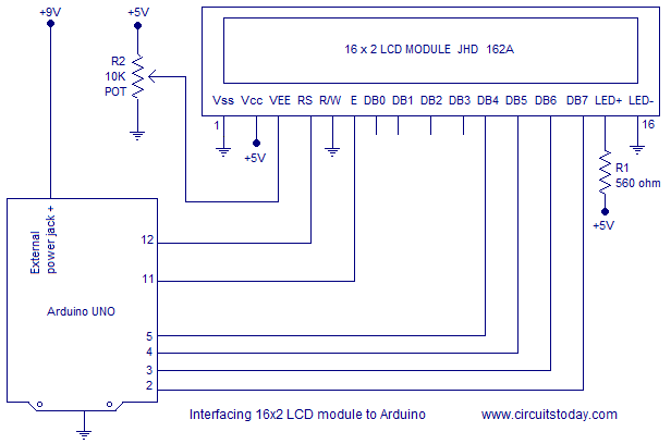
For knowing more about LCD module JHD162A and its pin functions, read this article: Interfacing 16×2 LCD and 8051 microcontroller. The circuit diagram of interfacing LCD to arduino for displaying a text message is shown below.
Read More: Display Text and Characters on LCD Screen using Arduino
- What is the most commonly used LCD module mentioned?
The 16x2 LCD Module is the most commonly used one, capable of displaying 32 ASCII characters across two lines. - How is the contrast adjusted on the JHD162A LCD?
Contrast is adjusted by connecting a 10K potentiometer between +5V and ground, with the slider pin connected to the VEE pin. - Can the JHD162A LCD operate in 8-bit mode?
Yes, the JHD162A can be operated in 8-bit mode using all 8 data lines, though this article uses 4-bit mode. - What is the function of the RS pin on the LCD?
The RS pin selects the register; Logic HIGH selects the data register while Logic LOW selects the command register. - How should the back light LED be powered in Arduino projects?
The back light LED can be powered from the 3.3V source on the Arduino board, or 5V with a 560 ohm resistor in series. - What happens when the E pin receives a HIGH to LOW signal?
A HIGH to LOW signal at the E pin enables the LCD module. - Which driver does the JHD162A module use?
The JHD162A is based on the HD44780 driver from Hitachi. - What is the purpose of the R/W pin?
The R/W pin selects between read and write modes, where Logic HIGH activates read mode and Logic LOW activates write mode.