Summary of Arduino Mosquito Repeller
This tutorial shows how to build an Arduino-based mosquito repellent shield that emits ultrasonic sounds (around 31 kHz) to deter mosquitoes and can be tuned between 23–54 kHz to also act as a dog whistle. The shield mounts onto an Arduino Uno, uses piezoelectric disks driven from digital pins, and can be adjusted for frequency and coverage. Construction involves soldering header pins, wiring piezo elements to pins 9 and 11 and ground, trimming the PCB to a shield shape, and optionally using a breadboard for prototyping.
Parts used in the Arduino Mosquito Repeller:
- Arduino Uno
- PCB
- Piezoelectric Disk
- Header Pins
- Breadboard (optional)
- Wires
- Soldering Iron
- Soldering Lead
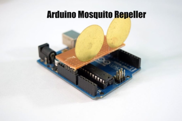
In this tutorial, I will demonstrate how to create a mosquito repellent device with the help of an Arduino. The repellent comes in a shield form that can be connected to the Arduino board, allowing for easy modification of its frequency.
This project is perfect for camping and hiking outdoor activities, as it emits a 31KHz Frequency sound that works as a mosquito repellent. This device can be tuned to different frequencies and also functions as a dog whistle between 23 kHz and 54 kHz. These frequency ranges are not detected by human ears.
You have the option to watch the video below to learn how to construct this project.
Step 1: Tools and Components
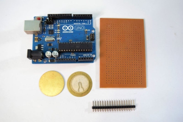
Here is a list of the components and tools required, the list is simple and all you need is
- Arduino Uno
- PCB
- Piezoelectric Disk
- Header Pins
- A breadboard (optional)
- Wires
- Soldering Iron
- Soldering Lead
Step 2: Measuring
This tutorial will show how to make a mosquito repellent device using an Arduino. The shield-shaped repellent can be attached to the Arduino board for simple adjustment of its frequency.
This project is ideal for outdoor camping and hiking activities, as it produces a 31KHz Frequency sound that acts as a mosquito repellent. This gadget has the ability to be adjusted to various frequencies and can also double as a dog whistle ranging from 23 kHz to 54 kHz. Human ears are unable to detect these frequency ranges.
You can choose to view the video below for instructions on how to build this project.
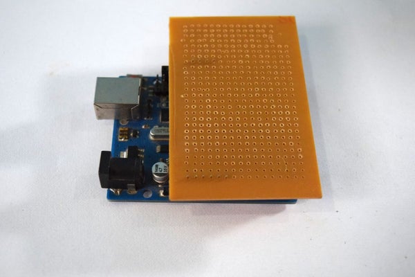
Step 3: Cutting
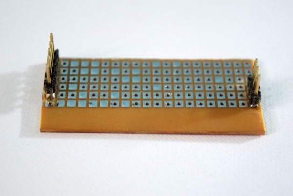
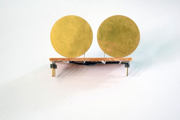
Once the headers are soldered, remove the extra PCB by cutting it with a rotary tool or a PCB cutter. Once you have cut the PCB, you should have a shield that looks similar to the one shown in the image. You have the option to smooth down uneven edges for a neater appearance.
Insert the board into the Arduino to ensure proper fitting.
Step 4: Circuit
The setup is straightforward – one piezoelectric disk is linked to digital pin 9 while the other is connected to digital pin 11. Both disks’ remaining terminals are joined and secured to the Arduino’s ground terminal. I am utilizing two digital pins in order to produce two distinct frequencies. If you prefer using just one frequency, you have the option to connect both disks in parallel.
Adjusting both disks to match the same frequency will result in the board vibrating in harmony, which will lead to an increased coverage area.
Read more: Arduino Mosquito Repeller
- What frequency does the device emit?
The device emits around 31 kHz and can be tuned between 23 kHz and 54 kHz. - Can the shield be attached directly to an Arduino?
Yes, the repellent is made as a shield that can be connected to the Arduino board. - Which Arduino pins are used for the piezo disks?
The tutorial connects one piezo disk to digital pin 9 and the other to digital pin 11. - Do both piezo disks share a ground connection?
Yes, the remaining terminals of both disks are joined and connected to the Arduino ground. - Can I use only one piezo disk instead of two?
Yes, you can use one frequency by connecting both disks in parallel or by using a single disk. - Why use two digital pins for the piezo disks?
Two pins allow producing two distinct frequencies for broader coverage. - Is the ultrasonic sound audible to humans?
No, the 23–54 kHz frequency ranges are not detected by human ears. - What tools are needed to shape the shield PCB?
The tutorial suggests using a rotary tool or a PCB cutter to remove extra PCB and smooth edges. - Is a breadboard required to build the project?
No, a breadboard is optional and can be used for prototyping.