Summary of Arduino – Control a DC motor with TIP120, potentiometer and multiple power supplies
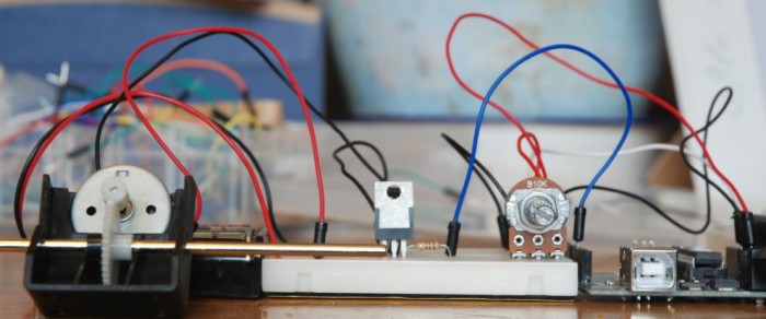
A simple Arduino circuit uses a potentiometer and a TIP120 transistor to PWM-control a DC motor powered by a separate higher-current supply. The Arduino reads the pot, maps it to 0–255 PWM on digital pin 9 through a 1 kΩ base resistor to the TIP120; motor power and Arduino GND must be common. A diode across the motor protects against back EMF. The example uses a 6 V motor and AA battery pack but supports other power supplies within component ratings.
Parts used in the TIP120 Arduino DC Motor Control Project:
- 1K Ohm resistor (Brown, Black, Red, Gold)
- 10K potentiometer
- TIP120 transistor
- 1N4004 1A diode
- 6V DC motor
- Arduino (Deumilanove w/ ATMEGA328 or similar)
- Breadboard or prototyping board
- Jumper/connector wires
- 4x AA battery holder
- 4x AA batteries
- Optional 9V DC power supply or USB power for the Arduino
A simple diagram demonstrating how to regulate the velocity of a DC motor using a potentiometer connected to your Arduino device. Additionally demonstrates the method of utilizing a TIP120 transistor for enabling the Arduino to manage a more powerful power source.
Transistors consist of 3 pins, with the third pin (Base) enabling control of the current flowing through the other two pins (Collector and Emitter). In this tutorial, I am utilizing the electrical power from the Arduino’s Digital PWM pin 9 (+5V) to regulate the current flow to a DC motor, which requires a separate power source with a significantly higher current capacity than what the Arduino board is capable of providing or managing. Every transistor is specifically designed for a particular operating range or current, as is typical for electrical components.
Displayed below are the pins of TIP120 along with their representation in a schematic diagram:
That is the transistor. The next component is the rectifier diode, which I am placing between the power supply and the motor. It functions as a unidirectional gate to restrict current flow in one direction, ensuring my circuit remains safe in case of a power surge from the motor power supply or excessive current draw by the motor. The primary point is that like LED’s, diodes have a proper orientation indicated on the left.
Another component is the potentiometer, which functions as a resistor that can be adjusted. You can regulate the current by adjusting how much is allowed to pass through when you turn it. Like resistors, potentiometers also have a resistance rating in Ohms and a power rating. I am using a potentiometer with a resistance rating of 10K ohms.
Arduino TIP120 Circuit Components
1K Ohm resistor (Brown, Black, Red, Gold)
10k Potentiometer
TIP120 Transistor
1n4004 1A Diode
6V DC motor
Arduino Deumilanove w/ ATMEGA328
Breadboard / Prototyping board
Jumper/ Connector wires
4x AA battery holder
4x AA batteries
Optional 9V DCpower supply or use the USB power for the Arduino
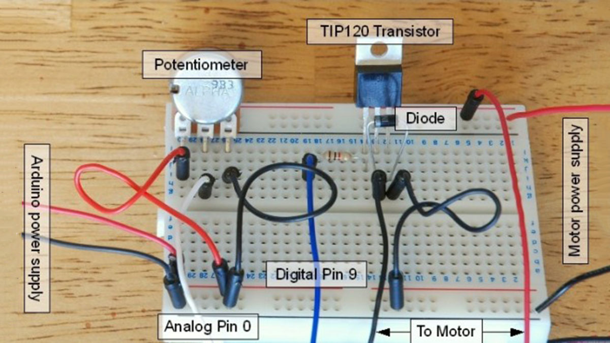
TIP120 Arduino DC Motor Control Circuit
Pretty simple, but remember that the GND connection must be shared between the Arduino and the additional power supply and I’m using a 1k Ohm resistor between Arduino pin 9 and the Base pin of the transistor.
TIP120 DC Motor Driver Sketch
int potPin = 0;                           // Analog pin 0 connected to the potentiometer
int transistorPin = 9;                  // connected from digital pin 9 to the base of the transistor
int potValue = 0;                       // value returned from the potentiometer

void setup() {                          // set  the transistor pin as an output
  pinMode(transistorPin, OUTPUT);
}

void loop() {                           // read the potentiometer, convert it to between 0 - 255 for the value accepted by the digital pin.
  potValue = analogRead(potPin) / 4;    // potValue alters the supply from pin 9 which in turn controls the power running through the transistor
  analogWrite(9, potValue);
}
For more detail: Arduino – Control a DC motor with TIP120, potentiometer and multiple power supplies
- How does the potentiometer control motor speed?
The Arduino reads the potentiometer on analog pin 0 and converts that value to a 0–255 PWM value which is written to digital pin 9 to vary motor speed. - Can the Arduino drive the motor directly?
No; the TIP120 transistor is used so the Arduino can control a separate higher-current power source for the motor. - Do I need to share grounds between power supplies?
Yes; the Arduino ground and the motor power supply ground must be common for the circuit to work correctly. - What is the purpose of the diode in the circuit?
The diode acts as a unidirectional gate to prevent reverse current and protect the circuit from back EMF or power surges from the motor. - What resistor is used between Arduino pin 9 and the TIP120 base?
A 1K Ohm resistor is used between Arduino pin 9 and the base of the TIP120. - Which Arduino pin is used for PWM control in the example?
Digital pin 9 is used for PWM control to the transistor base (via the 1K resistor). - What potentiometer value is used in the tutorial?
A 10K ohm potentiometer is used. - What motor and power source are demonstrated?
The tutorial demonstrates using a 6V DC motor powered by a 4x AA battery pack, with an optional 9V DC supply for the Arduino or USB power.