
Summary of Arduino MicroBot Project
This article outlines the assembly and testing of an Arduino MicroBot project. It details constructing two H-bridge circuits for bi-directional DC motor control and integrating QRD1114 line sensors. The process involves wiring components to a breadboard, verifying motor directionality with a test sketch, and calibrating sensors by identifying threshold values between light and dark readings to ensure accurate line detection.
Parts used in the Arduino MicroBot:
- Breadboard
- H-bridge circuits (bi-directional motor control circuits)
- Arduino
- DC motors
- QRD1114 line sensors
- Wires
Steps
On the breadboard, build two bi-directional motor control circuits (also known as “H-bridge”) circuits. These circuits will control the two DC motors that drive the wheels. Each circuit will have two wires from the Arduino (one for forward, one for backward) to control the circuit, and two wires from the single DC motor that it is controlling.
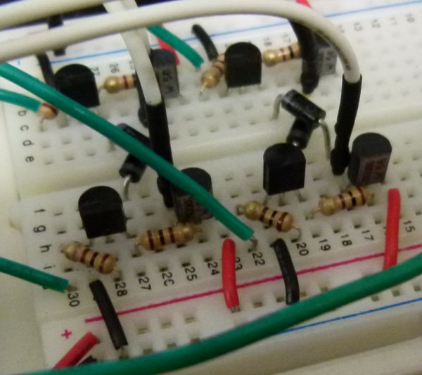
You should test your circuits to ensure you can control both motors in both forward and reverse directions. Here is a sample Arduino sketch you can use to test the motors. Edit the code to check each motor and direction, and double-check the circuit for any motor that doesn’t behave as expected.
Now, the QRD1114 line sensors need to be mounted and wired to the Arduino.
Now test that both QRD1114’s are operating correctly, and sending a proper signal to the Arduino.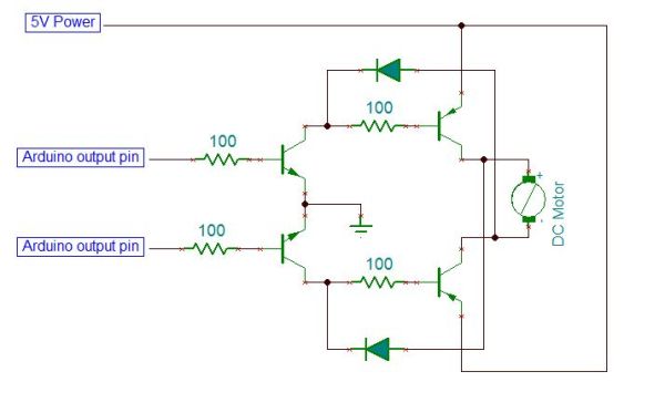 Here is a sample Arduino sketch to test the circuits. Make sure you are getting a good range of values from both sensors between light and dark. Make a not of the highest and lowest values you get from each sensor. You will use a value half way in between these for your “cut off” or “threshold” value. This is the boundary value we’ll use to decide if the sensor is seeing the dark line or not.
For more detail: Arduino MicroBot Project
- How many H-bridge circuits are required for this project?
Two bi-directional motor control circuits are needed to control the two DC motors that drive the wheels. - How do you wire the Arduino to the motor circuits?
Each circuit requires two wires from the Arduino to control forward and backward directions, plus two wires connecting to the single DC motor it controls. - What is the purpose of the sample Arduino sketch mentioned?
The sketch is used to test the motors to ensure they can be controlled in both forward and reverse directions. - Which sensors are mounted after testing the motors?
The QRD1114 line sensors need to be mounted and wired to the Arduino after the motor circuits are tested. - How do you determine the threshold value for the line sensors?
You must note the highest and lowest values from each sensor and use a value halfway in between as the cutoff or threshold value. - What signal should the QRD1114 sensors send to the Arduino?
The sensors must operate correctly and send a proper signal to the Arduino, showing a good range of values between light and dark. - Can you control the motors in both directions with these circuits?
Yes, the goal is to test the circuits to ensure you can control both motors in both forward and reverse directions.
