Summary of Arduino Keypad Garage Door Opener
This article details an Arduino-based garage door opener project using a Velleman 12-key keypad. The system employs a resistor network to detect key presses via analog voltage readings, controlling a relay that mimics the original opener's wire shorting mechanism. A program switch allows users to enter programming mode by resetting the Arduino while the switch is closed.
Parts used in the Arduino Keypad Garage Door Opener:
- Velleman 12 key keypad
- Arduino Uno or Duemilanove board
- 12 one K resistors
- 5 volt regulator
- 12 volt dongle power supply
- R13 15K resistor
- Q1 NPN silicon general purpose transistor (e.g., 2N2222)
- Schottky diode or normal diodes (1N914/1N4148)
- Radio Shack 275-0241 12VDC Relay
- SW1 program switch or jumper wire
About the circuit
The keypad has 13 connections. One for each key and one common. One side of each of the keypad switches goes to common and the other to one of the 12 key connections. I elected to build a resistor network as seen in the enclosed schematic. Click on the schematic to see a larger version that’s actually readable or visit http://fayettedigital.com/images/GDO.png in a separate window or tab. Thanks to Britton Kerin for the Arduino schematic symbol.
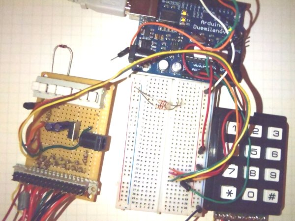
R13, the 15K resistor is present to assure that when nothing is pressed the returned ADC value is near 5 volts. Q1 is shown as a 2N2222 but any NPN silicon general purpose transistor will work. The diode across the coil of the relay should be a Schottky device, but I’ve gotten away with using normal diodes like a 1N914 or 1N4148. The relay I’m using is a Radio Shack 275-0241 12VDC Relay. Current draw is about 40 ma. It’s not shown on the schematic due to space constraints but the normally open contact and the common contact on the relay go to the opener. My original opener connected the wires briefly to open/close the door so this device will do the same. SW1 is the program switch. When the switch is closed and the Arduino is reset the software is placed into program mode. To return to normal mode open the switch and reset the Arduino. In the pictures you won’t see the switch. There are two reasons. In this reroll of the project, I’ve substituted a jumper wire for the switch. The other reason is that on version 1 of this project I rolled my own processor board and the switch is on it.
- How does the keypad detect which key is pressed?
A resistor network creates a voltage drop of about 0.42 volts per resistor, allowing the Arduino to measure relative voltage at the analog input when a key connects to common. - What power source drives the circuit?
The system is driven from a 12 volt dongle, utilizing a 5 volt regulator to provide power specifically to the Arduino. - Which transistor models are suitable for Q1?
Any NPN silicon general purpose transistor will work, though the schematic specifies a 2N2222. - Can I use normal diodes instead of a Schottky device?
Yes, you can get away with using normal diodes like a 1N914 or 1N4148 across the relay coil. - How do I put the software into program mode?
Closed the SW1 program switch and reset the Arduino to place the software into program mode. - What happens if I open the program switch and reset the Arduino?
Opening the switch and resetting the Arduino returns the device to normal operating mode. - Why was a jumper wire used instead of the switch in some pictures?
In a reroll of the project, a jumper wire substituted for the switch because version 1 had the switch on a custom processor board. - How does the relay interact with the garage door opener?
The normally open contact and common contact go to the opener to briefly connect wires, mimicking the original opener's action.