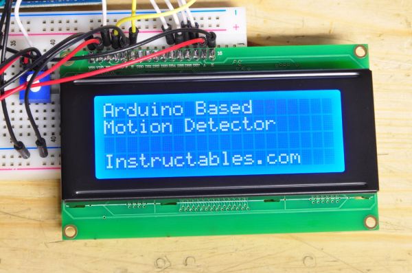
In this Instructable, I’ll be explaining how to build a motion activated alarm! It uses an Arduino microcontroller, a PIR (passive infrared) sensor, and a type of alarm. You can use an LED indicator, a buzzer, or a piezo. That’s the easy part. I will also be showing how to display to a character LCD screen, and over serial communication with a pair of XBee chips to relay the information to your computer! We will start with the basic LED lighting up though. That is also the best way to test the functionality of your PIR sensor to ensure it is working.

You should have a little bit of experience with Arduino to do this project. There is enough detail in this instructable to build it without but it would help to understand if you wanted to expand on it. Enough small talk, lets begin!
After uploading, open the serial terminal as well. The output can be read from there.
Step 1: Basic LED/Buzzer
1. Any Arduino or a deviation of it should work perfectly fine for this. $30 for the standard Uno. As long as it can be programmed by the Arduino IDE you will be fine.
2. A PIR sensor. I am using the Parallax PIR sensor. You can get it for about $10. The one from Adafruit should work fine if you set it on H (retrigger) which I will explain later. The one from SparkFun has the signal pin that goes LOW (off) on detection so there will be some code changing. I do not know exactly how that one outputs signals.
3. A prototyping breadboard will make this much easier. Otherwise you will be soldering pins. This should be anywhere from $5 to $15 depending on what kind you get.
The Parallax PIR sensor I use requires a 10-60 second warm up time in order to calibrate itself. It is best to have no movement while it is calibrating. I give it 30 seconds, which I incorporate into the code.
Here is how I have my PIR set up. It is built on a shield that fits over the Arduino but the pins are the same.
My PIR module has the jumper on the back set on H – retrigger. The pin will stay HIGH the motion is continuous. The signal pin is hooked up to Arduino pin 4. The LED is hooked up to Arduino pin 5. The other two white pins do not matter in the picture, those are soldered to my shield from another project.
During the warmup period, the red LED blinks two times per second. After 30 seconds, the LED will stop blinking rapidly. Generally the PIR will not blink that rapidly in normal use so you will know when the warmup period ends. Check the images for the wiring. Arduino PDE file is attached.
To use a buzzer, simply wire that up in place of the LED and remove the resistor. You should use a transistor if the buzzer is not a piezo and is in a white boxy form that generates the buzz by vibrating against a plastic piece.
Step 2: Wireless Transmission!
This part isn’t all that hard. You just need two XBee modules and a power supply for the receiver unit. It takes the very common 5.5mm center positive barrel jack. Input anywhere from 7v to 12v is fine. It also works fine at 6v from four AA batteries. It will not be enough to add an LCD since the voltage is actually slightly lower than 5v due to the voltage drop through the voltage regulator.
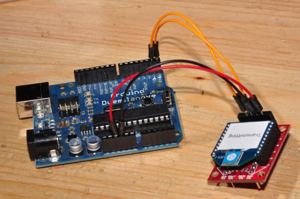
The easiest method would be an XBee shield plugged into the board and a receiver XBee on the other side. The receiver can be a simple XBee attached to an FTDI USB Serial converter.

You can use a simple XBee breakout board as well. If being used with a 5v Arduino, it MUST have a 5v to 3.3v logic circuit. 5v will toast an XBee. The SparkFun XBee Explorer and XBee Adapter Kit from Adafruit both have this circuit. Connect the Arduino TX pin to DIN on the XBee board and RX to DOUT.
The USB side will be the same. If using an XBee USB Adapter, it doesn’t need any kind of wiring. Program the XBees with the standard command set and 9600bps and you are set.
For more detail: Arduino Controlled Motion Sensor
