Summary of Spot Welder 1-2-3 Arduino Firmware
This article details the firmware and control circuit design for a DIY "1-2-3 Spot Welder." Unlike manual projects, this system automates a three-step welding process (warm-up, press, weld) using an Arduino microcontroller. It features configurable timings, persistent profile storage for different materials, and a user interface with an OLED display and rotary encoder to ensure professional-quality, repeatable welds.
Parts used in the 1-2-3 Spot Welder:
- Arduino Pro Mini 5V 16MHz
- Microwave Oven Transformer (MOT)
- BTA40 TRIAC
- MOC3052 Optocoupler
- Rotary encoder with push button
- 0.91 inch 128x32 I2C White OLED Display (SSD1306 based)
- Momentary push button with built-in LED
- HiLink HLK-5M05 mains power supply module
- CX1 X-type or Y-type capacitor for snubber network
- R3 Varistor rated for mains voltage peak
- Red indicator lamp for failure warning
Why another spot welder project?
Building a spot welder is one of the (arguably few) cases in which you can build something for a fraction of the price of the commercial version with comparable quality. And even if build-before-buy were not a winning strategy, it is a lot of fun!
So I decided to embark on the project, and I looked at how other people have done this. There is literally a ton of interesting information and videos about this on the net, with quite a wide variation in quality of design and build.
The quality of the build that one can realistically achieve depends on the tooling, machines, and facilities available, so it was not surprising to see quite a wide variation on this front. On the other hand, I was not expecting to see that most projects just use a simple manual switch to start and stop the welding process.
In fact, accurate welding time control is key to the quality of your welds, and you can not achieve that by flipping a switch by hand.
I felt that, while building yourself a spot welder is a topic that has been probably beaten to death already, maybe one could make a better machine by using the three-step welding process with accurate timings, as professional machines do. So I gave myself five main design goals for my project:
- Support for three-step welding process
- Accurate and configurable timings
- Ability to persistently store and retrieve welding profiles
- Simplicity of design and build
- Use of only commonly available components
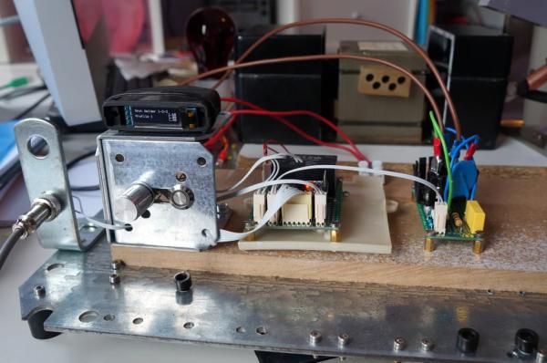
The result is my 1-2-3 Spot Welder, and in this instructable I will explain the welding process control part of the project. The video and this instructable show pictures of the prototype test welder, before all components are mounted into a proper case. A board for this project is described in a separate instructable.
If you need to familiarize yourself with the concept of resistance welding and how one can make a welder using a microwave transformer, please do so before you read on. I will concentrate of the control of the welder, not on how a welder works or how to build one. I feel this this is well covered elsewhere.
Step 1: Recipe
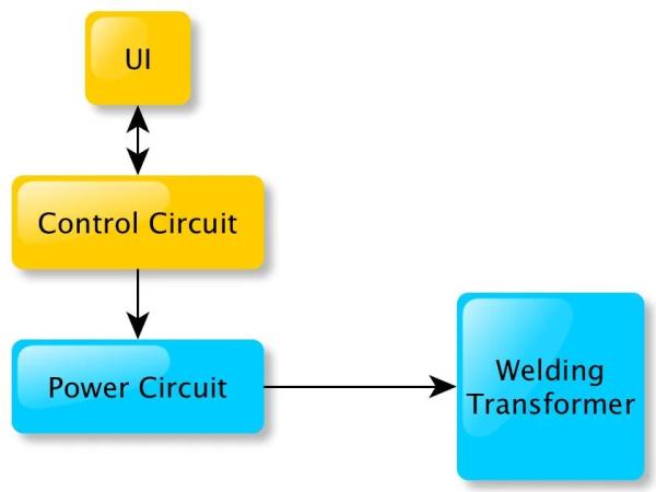
Let’s look at a the components of resistance welder:
- Welding transformer. Provides the low voltage/high current output necessary for resistance welding by conversion of the AC line voltage. For a self-made welder the welding transformer is normally obtained by converting a Microwave Oven Transformer for low-voltage, high-current output. This is done by removing the high voltage secondary winding from the MOT and winding a new secondary consisting of a few turns of a very thick copper cable. There are a lot of videos on YouTube that show you how to do this.
- Power Circuit. Switches the welding transformer on and off, and its operation is controlled by the Control Circuit. The Power Circuit operates at mains voltage.
- Control Circuit. Controls all operations for the welder:
- Allows the user to set and change welding timings.
- Allows the user to store and retrieve welding timings.
- And, last but not least, allows the user to start a welding process by sending commands to the Power Circuit, which turns the transformer on and off.
- UI. The user communicates with the Control Circuit via a User Interface.
This instructable describes the UI and Control Circuit. The UI and Control Circuit design I propose are actually quite independent from the other blocks and can be easily retrofitted to an existing spot welder, provided your current incarnation of the Power Circuit can handle the digital output signal from the Control Circuit. So if you already have an electronically switched welder you can add the control and UI components described here on top of that with no other modifications.
If you just have a manual power switch right now, you will also need to build a Power Circuit.
Before describing the operation of the firmware for the Control Circuit, let’s see a bit more in detail how the welding process works.
Step 2: 1-2-3 Welding
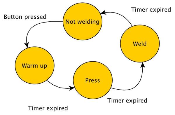
Professional welding machines do not weld in one step; they use an automated three-step sequence. Three-step resistance welding consists of:
- Warm-up step. Welding transformer is switched on, and current flows via the electrodes through the work pieces. This is meant to just warm up the metal.
- Press step: Welding transformer is switched off; the work pieces are maintained tightly pressed against each other. The softened hot metal work pieces surfaces make very good mechanical and electrical contact now.
- Weld step: Welding transformer is switched on again. The metal surfaces now in intimate contact are welded under pressure.
The duration of the individual steps is in general not uniform and depends from the available current from the welder, the type of material you are trying to weld (mainly its resistance and melting point), and the thickness of the work pieces.
Many of the self-built welders I learned about do not have automated timing control, which makes repeatable and reliable operation very difficult.
Some do have the ability to set a welding time, often via a potentiometer. Kerry Wong has done a very nice one in this class with an extra pair of electrodes specifically to weld batteries.
Very few self-built welders are able to automatically execute the three welding steps as described above. Some have only with one set of fixed durations, like this one and this one. With others you can change some of the durations, like with this one . It has a fixed duration for the warm-up and press steps, while the duration of the weld step can be changed via a potentiometer.
This makes the process partially adjustable, but it may be difficult to find a setting again when you want to weld again that particular battery tab material after some time has passed. Once you have found the right timings for a particular material and thickness combination, you don’t want to have to do it all over again. It’s a waste of time (and material), and it can be a bit frustrating.
What you (well, I) really want here is complete flexibility (configurability) for all timings and the ability to store and retrieve settings once we got them right.
Fortunately, it’s not that hard. Let’s see how to control three-step resistance welding.
Step 3: 1-2-3 Welding Control
We implement the Control Circuit with a microcontroller (MCU). The MCU firmware operates as a state machine with four states like we saw in the previous step:
o State 0: Not welding
o State 1: Welding, warm-up step
o State 2: Welding, press step
o State 3: Welding, weld step
I am using C-style pseudo code to describe the program flow here because it is easy to relate it to the actual MCU code that is written in C/C++.
After the setup step, the MCU main loop handles user input and state transitions as follows:
01: loop
02:   switch (state) {
03:     case 0:
04:        readUserInput
05:     case 1,2,3:
06:       if ( welding timer has expired ) {
07:         // move to the next state
08:        state = (state + 1) % 4;
09:        toggle power control
10:        if ( state is not 0 ) {
11:          set the new step duration and restart welding timer
12:          }
13:        }
14: end loop
If the current state is 0, then we read the UI state to process user input and move on to the next iteration.
We use a welding timer to controls the duration of the welding steps. Assume now the welding sequence has just started when we enter the switch statement. Power control is on, the welding transformer is energized, and the current state is 1.
If the welding timer has not expired the conditional (line 6) evaluates to false, we exit the switch statement and move on to the next event loop iteration.
If the welding timer has expired, we enter the conditional (line 6) and move on:
1. Calculate and save the next state (line 8). We use modulo 4 arithmetic to follow the correct state sequence 1-2-3-0. If the current state was 1, we move now to state 2.
2. Then we toggle the power control (line 9). In state 1 the power control was on, so now it is off (as it should be in state 2, press step, with the welding transformer not energized).
3. The state is now 2, so we enter the conditional on line 10.
4. Set the welding timer for the new step duration (duration of the press step) and restart the welding timer (line 11).
The following iterations of the main loop will be pretty uneventful until the welding timer expires again, i.e. the press step is completed.
At this time we enter the body of the conditional on line 6. The next state (state 3) is computed on line 8; power to the transformer is switched on again (line 9); the welding timer is set to the duration of the weld step, and restarted.
When the timer expires again, the next state (state 0) is computed on line 8, but now line 11 is not executed, so the timer is not restarted as we are finished with the welding cycle.
On the next loop iteration we are back to processing user input (line 4). Done.
But how do we start the welding process at all? Well, we start when the user presses the welding button.
The welding button is connected to an MCU input pin, which is attached to a hardware interrupt. Pressing the button causes an interrupt to occur. The interrupt handler starts the welding process by setting the state to 1, setting the welding timer to the duration of the warm-up step, starting the welding timer, and switching the power control on:
19: startWelding
20:   state = 1
21:   set the warm-up step duration and start welding timer
22:   switch on power control
23: end startWelding
Step 4: UI Management, Standby, and Other Firmware Complications
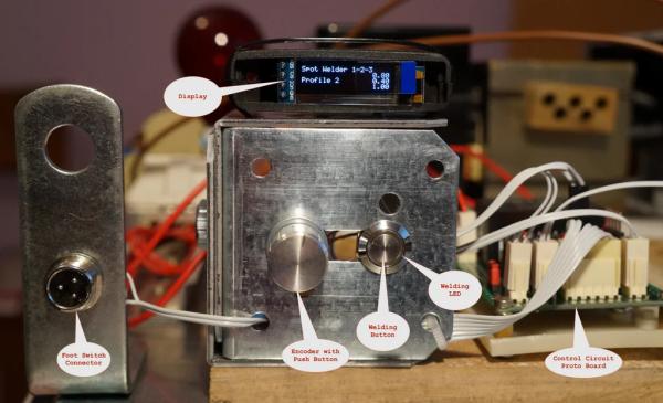
The UI consists of a display, an encoder with push button, a momentary push button, and a led. They are used as follows:
- The display provides feedback to the user for configuration, and shows progress during welding.
- The encoder with push button controls all interaction with the firmware, except starting a welding sequence.
- The momentary push button is pressed to start a welding sequence.
- The led is lit during a welding sequence, and is faded repeatedly in and out during standby.
There are a number of things the firmware has to do beyond controlling the welding process as explained in the previous step:
- Reading user input. This involves reading the encoder position and button status. The user can rotate the encoder left or right to move from one menu item to the next and to change parameters on the display, or can press the encoder button to confirm a value entered or to move one level up the menu structure.
- Updating the UI.
- The display is updated to reflect user actions.
-
- The display is updated to reflect progress of the welding process (we show an indicator next to the duration of the current step in the welding sequence)
-
- The led is switched on when we start welding and off when we are finished.
- Standby. The code keeps track of how long the user has been inactive, and enters standby when the inactivity period exceeds a preset limit. In standby, the display is switched off, and the led on the UI is faded repeatedly in and out to signal the standby condition. The user can exit standby by rotating the encoder in either direction. When in standby, the UI should not react to other user interactions. Notice that the welder only is allowed to enter standby when it is in state 0, e.g. not while it is welding.
- Defaults management, storing and retrieving profiles. The firmware supports 3 different welding profiles, i.e. settings for 3 different materials/thicknesses. The profiles are stored in flash memory, so they will not be lost when you power off the welder.
In case you are wondering, I have added the standby feature to prevent burn-in of the display. When the welder is powered and you are not using UI, the characters shown on the display do not change, and may cause burn in. Your mileage may vary depending on display technology, however I am using an OLED display, and they are prone to burn in pretty quickly if left uncared for, so having automatic display switch off is a good idea.
All the above complicates of course the “real” code. You can see there is a bit more work to do than what we have looked at in the previous steps to get a nicely wrapped piece of software.
This confirms the rule that with software the implementation of what you build around the core functionality is often more complex than the implementation of the core functionality itself!
You will find the complete code in the repository link at the end of this instructable.
Step 5: Control Circuit
The firmware has been developed and tested using these components:
- Control Circuit:
- Arduino Pro Mini 5V 16MHz
- UI:
- Rotary encoder with push button
- 0.91” 128×32 I2C White OLED Display DIY based on SSD1306
- Momentary push button with built-in led
Of course you don’t need to use exactly these components in your build, but may have to make some code modifications if you don’t, especially if you change display interface, type, or size.
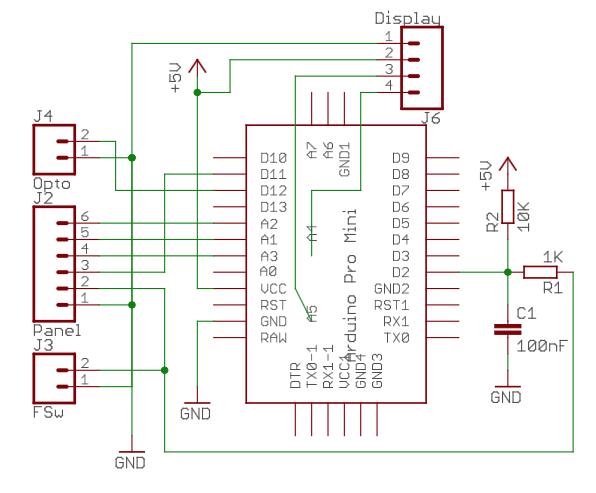
Arduino Pin Assignment:
- Input:
- Pins A1 A2 A3 to rotary encoder used to select/change profiles and parameters
- Pin 2 connected to a temporary push button that is pressed to start welding. The push button is normally mounted to a panel next to the encoder, and can be connected in parallel to a pedal switch.
- Output:
- Pins A4/A5 for I2C controlling the display.
- Pin 11 for digital output to the led, which is switched on during a welding cycle, and faded in and out during standby. There is no current limiting resistor for the led in the schematic because I used a led built into the welding button that came with a series resistor. If you use a separate led you will need to either add a resistor in series between pin 11 of the Pro Mini and pin 3 of connector J2, or solder it in series with the led on the front panel.
- Pin 12 for digital output to the mains power circuit (input to power circuit). This pin is normally LOW and will go HIGH-LOW-HIGH during a welding cycle.
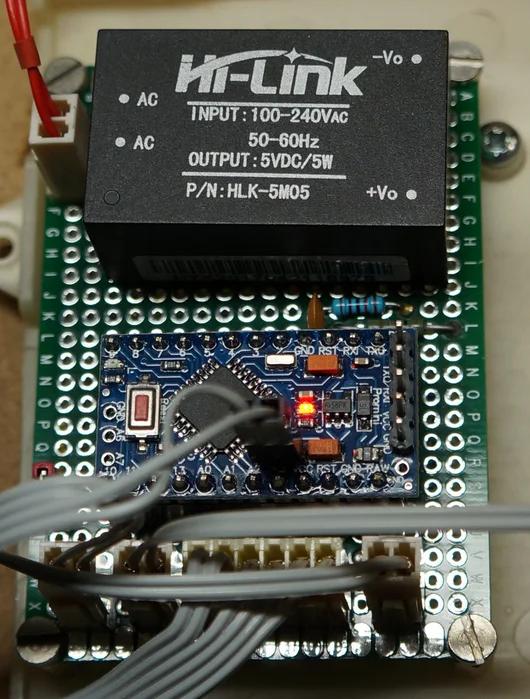
After prototyping on a breadboard, I have mounted the control circuit on a self-contained proto board including a mains power supply module (HiLink HLK-5M05), the capacitor and resistors to debounce the welding button, and connectors for display, encoder, led, button, and power circuit output. The connections and components are shown in the schematic (except the mains power supply module).
There is also a connector (J3 in the schematic) for a foot switch connected in parallel to the welding button, so one can start welding either from the panel or using a foot switch, which I find way more convenient.
The J4 connector is connected to the optocoupler input of the power circuit, which is mounted on a separate proto board in the prototype.
For the connection to the display (J6 connector), I actually found it easier to use a 4 wires flat cable with two wires going to a two pin-connector (corresponding to pins 1,2 of J6), and two wires with Dupont female connectors going directly to pins A4 and A5. On A4 and A5 I soldered a two-pin male header directly on top of the Pro Mini board.
I will probably add debouncing for the encoder button as well in the final build. An improved PCB design for this project is described in a separate instructable.
Step 6: Power Circuit
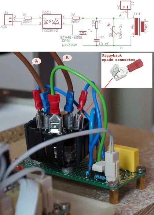
The schematic for the power circuit is very standard for a control of an inductive load with a TRIAC. The signal from the control control circuit drives the emitter side of the MOC1 optocoupler, the detector side in turn drives the gate of the T1 triac. The triac switches the load (the MOT) via a snubber network R4/CX1.
Optocoupler. The MOC3052 is a random phase optocoupler, not the zero-crossing type. Using random-phase switching is more appropriate than zero-crossing switching for an heavy inductive load such as the MOT.
TRIAC. The T1 triac is a BTA40 rated for 40A continuous on-state current, which may seem an overkill in terms of the current drawn by the MOT in steady state. Considering that the load has a quite high inductance however, the rating we need to be concerned about is the non repetitive surge peak on-state current. This is the inrush current of the load. It will be drawn every time during the switch-on transient by the MOT, and it will be several times higher than the on-state current. The BTA40 has a non repetitive surge peak on-state current of 400A at 50 Hz and 420A at 60 Hz.
TRIAC package. One more reason to select a BTA40 is that it comes in an RD91 package with insulated tab and has male spade terminals. I don’t know about you, but I rather prefer an insulated tab for power semiconductors at mains voltage. Additionally, the male spade terminals offer a solid mechanical connection that allows to keep the high current path (wires marked A in the schematic) completely off the proto or PCB board. The high current path goes via the (thicker) brown wires marked A in the picture. The brown wires are connected to the triac spade terminals via piggyback terminals that are also connected to the RC net on the board via the (thinner) blue wires. With this mounting trick the high current path is off the proto or PCB board. In principle you could do the same with soldering wires on the legs of the more common TOP3 package, but the assembly would be mechanically less reliable.
For the prototype I have mounted the triac on a small heatsink with the idea of taking some temperature measurements and possibly mounting it on a larger heatsink or even in direct contact with the metal case for the final build. I observed that the triac barely warms up, partly because it is appropriately oversized, but mainly because most power dissipation in the junction is due to conduction state switching and the triac clearly does not switch frequently in this application.
Snubber network. R4 and CX1 are the snubber network to limit the rate of change seen by the triac when the load is switched off. Don’t use any capacitor you may have in your spare parts bin: CX1 must be an X-type (or better Y-type) capacitor rated for mains voltage operation.
Varistor. R3 is a varistor sized accordingly your mains voltage peak value. The schematic shows a varistor rated for 430V, which is appropriate for 240V mains voltage (careful here, the voltage rating in the varistor code is a peak value, not an RMS value). Use a varistor rated for 220V peak for a 120V mains voltage.
Component Failure. It is good practice to ask yourself what the consequences component failure would be and identify the worst scenarios. A bad thing that could happen in this circuit is the triac failing and shorting the A1/A2 terminals. If this happens the MOT would be permanently energized as long as the triac is shorted. If you were not to notice the transformer hum and would weld with the MOT permanently on you would overheat/ruin workpiece/electrodes (not nice), and possibly overheat/melt cable isolation (very bad). So it is a good idea to build in a warning for this failure condition. The easiest thing is to connect a lamp in parallel to the MOT primary. The lamp will light up when the MOT is on, and provide a visual cue that the welder is working as intended. Should the light go on and stay on, then you know it is time to pull the plug. If you have watched the video at the beginning you may have noticed a red light bulb going on and off in the background during welding. This is what that red light is.
An MOT is not a very well behaved load, but despite being initially a bit concerned about the reliability of the switching via the power circuit, I have not seen any problems.
Step 7: Final Notes
Well, first thanks a lot to the many people who have taken the time to explain on the net how to build a spot welder using a repurposed microwave oven transformer. This has been a huge bootstrap for the whole project.
As far as Spot Welder 1-2-3 firmware is concerned, it would have been a long and tedious work to write the code without the abstractions provided by a number of libraries in addition to the standard Arduino IDE. I find these timer (RBD_Timer), encoder (ClickEncoder), menus (MenuSystem), and EEPROM (EEPROMex) libraries very useful.
The firmware code can be downloaded from the Spot Welder 1-2-3 code repository.
If you plan to build this I strongly suggest to use the PCB design described here, which incorporates a number of refinements.
If you build a complete spot welder please be aware that it operates at mains power and with high current!
- How does the three-step welding process work?
The process involves a warm-up step where current flows to heat the metal, a press step where power is off but pressure maintains contact, and a final weld step where power returns to fuse the metals. - Can I use this control system on an existing spot welder?
Yes, the UI and Control Circuit are independent and can be retrofitted to an existing welder if its Power Circuit can handle the digital output signal. - What components are required for the Control Circuit?
The core components include an Arduino Pro Mini 5V 16MHz, a rotary encoder with push button, an OLED display, and a momentary push button with an LED. - Why is a random phase optocoupler preferred over zero-crossing?
A random phase optocoupler like the MOC3052 is more appropriate for heavy inductive loads such as a Microwave Oven Transformer compared to zero-crossing types. - How does the system prevent display burn-in?
The firmware includes a standby mode that turns off the display after a period of user inactivity to prevent characters from burning into the screen. - Can I store multiple welding profiles?
Yes, the firmware supports storing up to three different welding profiles in flash memory so settings are not lost when power is turned off. - What safety feature warns of a shorted triac?
A red lamp connected in parallel to the MOT primary lights up when the transformer is energized; if it stays on continuously, it indicates the triac may have failed and shorted. - Is it possible to start welding with a foot switch?
Yes, a foot switch can be connected in parallel to the main welding button via connector J3 to allow hands-free operation.