Here is a project I made a couple of years ago for my father’s car. The original dashboard’s info-panel which displayed current time, date and temperature was working only partly – and that only after a good cleaning and connector fastening. In other words – it wasn’t really usable, so I made an Arduino replacement.
The new panel features:
- Big 8-character LCD display with auto-on adjustable white backlight
- 2 x DS18B20 I²C temperature sensors
- Two control buttons from the old panel (duplicated for accessibility) and a potentiometer (for manual LCD backlight adjustment)
- Automatic fading LCD backlight on/off depending on the headlight state
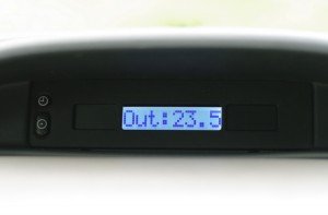
- Software: Current date/time, voltage and in/out temperature with ability to adjust the date/time through menu. Displays one (selectable) item at a time or cycles them with various time intervals.
 A menu for manually setting the date and time using the buttons
- Ability to synchronize the time and date from a computer by sending a Time command to the serial port
One of the main requirements was to use a display with good, readable characters. The JHD704-801_8 character LCD_display seemed to be the best choice according to physical and character size. I removed the old display and saw off most of the old circuit board leaving only the part with buttons because I wanted to reuse them. As the new display was shorter I had to tape the side windows – I used plastic from an ice-cream lid, cut it to size and taped with a black-matt adhesive paper.
I reused an old FDD ribbon cable from for the display and traced the traces for the buttons and soldered 3 wires – one for common ground and one for each button. The display itself is held in place with hot glue. The loose black and red wires in the pictures above are for the LCD backlight.
Once the new display was in place I could upload some sample Arduino sketch and test how does it look. To connect the display to the Arduino I made some custom header pins. The power lines were soldered on a separate board and so did the temperature sensor sockets for easier – modular access and connectivity.
Next is a power input board with a voltage divider using two resistors to measure the battery’s voltage.
I doubled the buttons near the LCD display to a separate switch for easier access.
After a while I moved to Arduino Nano which has basically the same functionality but only in smaller size factor.
You can download the source code the whole project files Car_LCD_Display or just the Arduino sketch (V0.23). The latest software version with libraries and schematics can be obtained from my Bitbucket repository:
https://bitbucket.org/KristoZ/arduino-car-lcd-display/src
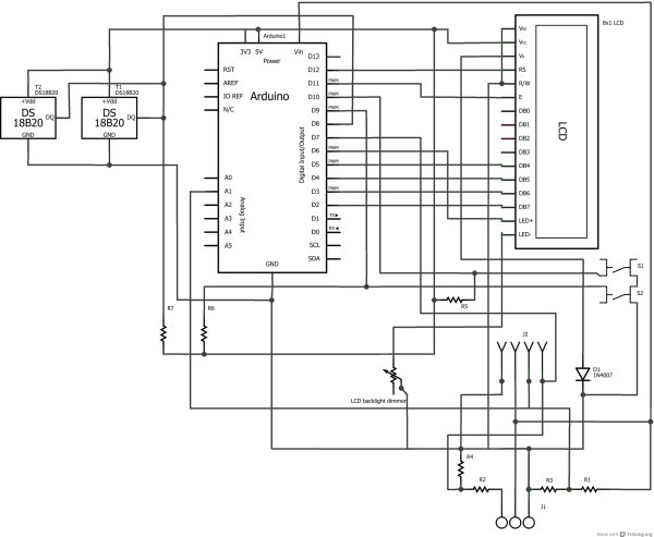
Here is the circuit diagram as a ‘breadboard view’:
The diode D1 is needed to get the optimal contrast if the system is powered by car’s 12 volts. If the power supply is <=5V then the contrast pin can be connected directly to ground to get the best contrast. The buttons S1 and S2 are connected in parallel with a centered ON-OFF-ON switch (in the photos above) for ‘remote’ control as the display is rather far in the dash. The temperature sensors T1 and T2 are connected in parallel because they both utilize I2C port and there is a connector in-between the system (not shown in the diagrams). The connector J2 is shown directly connected to the outgoing wires, but actually there is a separate jack for wires VIN (+12V), GND, remote light pin D7 and voltage monitor pin A1. The connector J1 has the input pins to the remote lights pin (+12V), battery (+12V) and a ground accordingly from left to right in the circuit diagram. It is reverse in the breadboard view.
Parts list:
- Arduino Duemilanove/Uno/Nano
- 1-line/8-character LCD display. Can be used with standard 2 or even 4-line displays as the pin-out is the same, but the code is optimized for the 8-character one.
- 2x DS18B20 temperature sensors. Can be used with up to 127(!) I2C sensors. They basically have ±0.5°C precision, but the code is tweaked to use the best 0.1 (0.0625)°C resolution.
- 25k linear rotary shaft potentiometer for LCD backlight maximum brightness adjustment. Anything from 10k to 50k should do fine.
- 2x 100k 1/4W resistors (R1 and R2) for the voltage divider
- 2x 47k 1/4W resistors (R3, R4) for the voltage divider
- 2x 10k resistors (R5, R6) for the push-buttons (S1 and S2)
- 1x 4.7k pull-up resistor (R7) for the I²C bus
- 3-pin screw terminal for the power supply and remote headlight signal (J1), as well as some other terminals and connectors, 7-13AWG – and some jumper-wires. Push-buttons were reused from the old panel.
- Some single-sided prototyping perfboard, heat-shrinks and insulation tape are recommended in addition to basic soldering equipment. The resistors may be 1/8W-rated or even less, because the current draw is rather small through them.
Car LCD display with RTC
The system above works pretty great at displaying temperatures, but if you don’t keep your car in a heated garage then the temperature changes make the already inaccurate built-in clock even worse and you will see a reasonable offset in time even in even less than a couple of hours. Also, if you don’t have a direct connection to your car’s battery, then you’ll lose the current time settings every time you take out the keys of the ignition. So what can be done to resolve these issues?
Well, you could add an external real time clock (RTC) like Dallas DS1307 which is rather cheap and simple solution for adding external time-keeper to your Arduino-based system. But still it won’t solve the problem with the precision, that’s why you’ll need a temperature-compensated real time clock like the more expensive DS3234 (I got one from E-bay for less than a half the price at about 6£ or ~$10).
 The implementation was rather easy once I got the new DS3234RTC library working. I took the liberty of creating a new library by assembling it from various sources, as the existing ones I found were either overly complicated, could not use the Time library, not working as expected or were embedded directly in the main sketch making it much more complicated. My main goal was to make the new library as similar to the DS1307RTC library as possible which is bundled with the Time library from Arduino website because I like the simplicity of it. The only bigger difference is that the new library needs the “RTC.begin(8);” line in the setup section of the code defining a “chip-select” (SS) pin to use.
The DS3234 RTC uses SPI connection so I had to move some of the pins:
- Digital pins 12 and 11 to 10 and 9 correspondingly
- Button pins 10 and 9 to the analog 2 and 3 (in the code as 16 and 17)
- The “headlight-on” sensing D7 pin to A0
- And the I²C data wire from D8 to D7
For more detail: Arduino car LCD display