Summary of Arduino Based Guitar Tuner
This article describes a DIY Arduino-based guitar tuner project aimed at helping guitarists tune their instruments by measuring string frequencies. It explains musical note frequencies, standard guitar tuning, and the process of converting guitar sounds into frequencies using amplification, offsetting, and analog-to-digital conversion (ADC) with an Arduino Uno. The project uses pushbuttons to select strings, LEDs to indicate tuning status, and an Arduino program to analyze sound frequencies and guide tuning adjustments. The guide includes components, circuit schematics, and code snippets.
Parts used in the DIY Arduino Guitar Tuner:
- Arduino Uno x1
- LM386 amplifier x1
- Condenser Microphone x1
- Microphone / Audio jack x1
- 10k potentiometer x1
- 0.1µF capacitor x2
- 100 ohms resistor x4
- 10 ohms resistor x1
- 10µF capacitor x3
- 5mm yellow LED x2
- 5mm green LED x1
- Normally Open Push Buttons x6
- Jumper wires
- Breadboard
Hi guys, during the last few weeks, I’ve been working on reconnecting with my love for the guitar. Playing the box guitar was how I relax few years back before the saxophone took over. Going back to the guitar, after 3 years of rarely strumming a chord, I discovered amongst other things that I no longer knew how each of the string should sound, to put it in my friend’s words, “My hearing was no longer tuned” and as a result of this, I was not able to tune the guitar without the aid of a keyboard or a mobile app which I later downloaded. The weeks went by till few days ago when the maker in me became motivated and I decided to build an Arduino based Guitar Tuner. In today’s tutorial, I will be sharing how to build your own DIY Arduino Guitar Tuner.
How Guitar Tuner Works
Before we move to the electronics, its important to understand the principle behind the build. There are 7 major musical notes denoted by the alphabets; A, B, C, D, E, F, G and usually end with another A which is always at an octave higher than the first A. In music several versions of these notes exists like the first A and the last A. These notes are distinguished each one from their variation and from one another by one of the characteristics of sound known as pitch. Pitch is defined as the loudness or lowness of sound and its indicated by the frequency of that sound. Since the frequency of these notes are known, for us to determine if the guitar is tuned or not, we only need to compare the frequency of the note of particular string to the actual frequency of the note that the string represents.
The frequencies of the 7 musical notes are:
A = 27.50Hz
B = 30.87Hz
C = 16.35Hz
D = 18.35Hz
E = 20.60Hz
F = 21.83Hz
G = 24.50 Hz
Each variation of these notes is always at a pitch equal to FxM where F is the frequency and M is a non-zero integer. Thus for the last A which as described earlier, is at an octave higher than the first A, the frequency is;
27.50 x 2 = 55Hz.
The guitar (Lead/box guitar) usually has 6 strings denoted by the notes E, A, D, G, B, E on open string. As usual, last E will be at an octave higher than the first E. We will be designing our guitar tuner to help tune the guitar using the frequencies of these notes.
According to the standard guitar tuning, the note and corresponding frequency of each string is shown in the table below.
Strings | Frequency | Notation |
1 (E) | 329.63 Hz | E4 |
2 (B) | 246.94 Hz | B3 |
3 (G) | 196.00 Hz | G3 |
4 (D) | 146.83 Hz | D3 |
5 (A) | 110.00 Hz | A2 |
6 (E) | 82.41 Hz | E2 |

The project flow is quite simple; we convert the sound signal generated by the guitar to a frequency then compare with the exact frequency value of the string being tuned. The guitarist is notified using an LED when the value correlates.
The frequency detection/conversion involves 3 main stages;
- Amplifying
- Offsetting
- Analog to Digital conversion(sampling)
The sound signal being produced will be too weak for the Arduino’s ADC to recognize so we need to amplify the signal. After amplification, to keep the signal within the range recognizable by the Arduino’s ADC to prevent clipping of the signal, we offset the voltage of the signal. After offsetting, the signal is then passed to the Arduino ADC where it is sampled and the frequency of that sound is obtained.
Required components
The following components are required to build this project;
- Arduino Uno x1
- LM386 x1
- Condenser Mic x1
- Microphone / Audio jack x1
- 10k potentiometer x1
- O.1uf capacitor x2
- 100ohms resistor x4
- 10ohms resistor x1
- 10uf capacitor x3
- 5mm yellow LED x2
- 5mm green LED x1
- Normally Open Push Buttons x6
- Jumper wires
- Breadboard
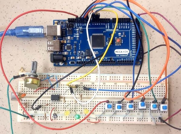
Schematics
Connect the components as shown in the Guitar Tuner Circuit Diagram below.
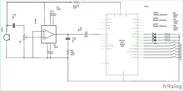
The push buttons are connected without pull up/down resistors because the Arduino’s in built pullup resistors will be used. This is to ensure the circuit is as simple as possible.
Arduino Code for Guitar Tuner
The algorithm behind the code for this Guitar Tuner Project is simple. To tune a particular string, the guitarist selects the string by pressing the corresponding pushbutton and strums the plays an open string. The sound is collected by the amplification stage and passed on to the Arduino ADC. The frequency is decoded and compared. When the input frequency from the string is less than the specified frequency, for that string one of the yellow LEDs come on indicating that the string should be tightened. When the measured frequency is greater than the stipulated frequency for that string, another LED comes on. When the frequency is within the stipulated range for that string the green LED comes on to guide the guitarist.
Complete Arduino code is given at the end, here we have briefly explained the important parts of code.
We start by creating an array to hold the switches.
int buttonarray[] = {13, 12, 11, 10, 9, 8}; // [E2, A2, D3, G3, B3, E4]
Next, we create an array to hold the corresponding frequency for each of the strings.
float freqarray[] = {82.41, 110.00, 146.83, 196.00, 246.94, 329.63};//all in Hz
With this done, we then declare the pins to which the LEDs are connected and other variables that will be used for obtaining the frequency from the ADC.
int lowerLed = 7;
int higherLed = 6;
int justRight = 5;
#define LENGTH 512
byte rawData[LENGTH];
int count;
Next is the void setup() function.
Here we start by enabling the internal pull up on the Arduino for each of the pins to which the switches is connected. After which we set the pins to which the LEDs are connected as outputs and launch the serial monitor to display the data.
void setup()
{
for (int i=0; i<=5; i++)
{
pinMode(buttonarray[i], INPUT_PULLUP);
}
pinMode(lowerLed, OUTPUT);
pinMode(higherLed, OUTPUT);
pinMode(justRight, OUTPUT);
Serial.begin(115200);
}
Next, is the void loop function, we implement the frequency detection and comparison.
void loop(){
if (count < LENGTH)
{
count++;
rawData[count] = analogRead(A0)>>2;
}
else {
sum = 0;
pd_state = 0;
int period = 0;
for(i=0; i < len; i++)
{
// Autocorrelation
sum_old = sum;
sum = 0;
for(k=0; k < len-i; k++) sum += (rawData[k]-128)*(rawData[k+i]-128)/256;
// Serial.println(sum);
// Peak Detect State Machine
if (pd_state == 2 && (sum-sum_old) <=0)
{
period = i;
pd_state = 3;
}
if (pd_state == 1 && (sum > thresh) && (sum-sum_old) > 0) pd_state = 2;
if (!i) {
thresh = sum * 0.5;
pd_state = 1;
}
}
// Frequency identified in Hz
if (thresh >100) {
freq_per = sample_freq/period;
Serial.println(freq_per);
for (int s=0; s<=5; s++)
{
if (digitalRead(buttonarray[i])== HIGH)
{
if (freq_per – freqarray[i] < 0)
{
digitalWrite(lowerLed, HIGH);
}
else if(freq_per – freqarray[i] > 10)
{
digitalWrite(higherLed, HIGH);
}
else
{
digitalWrite(justRight, HIGH);
}
}
}
}
count = 0;
}
}
The complete code with a demonstration video is given below. Upload the code to your Arduino board and strum away.
Read More Information: Arduino Based Guitar Tuner