Summary of An FM Stereo Broadcaster PLL using Arduino
The article describes the creation of a high-quality, frequency-stable FM Stereo Broadcaster using an Arduino to control the Niigata Seimitsu NS73M FM transmitter module. The device includes a 16x1 LCD for frequency display, user controls for frequency setting, and EEPROM storage of last-used frequency. The system achieves excellent audio quality and stable frequency over the full US FM broadcast band at low cost, surpassing many commercial alternatives. The project uses pre-existing modules integrated with custom Arduino code and is housed in a metal enclosure for RF shielding.
Parts used in the FM Stereo Broadcaster:
- Arduino (Bare-Bones Board from Modern Device Company)
- NS73M FM Transmitter module (Niigata Seimitsu Co., breakout board from SparkFun Electronics)
- 16x1 LCD display (Varitronix, from AllElectronics.com)
- Push buttons (Up, Down, Set)
- 3.3V voltage regulator (for NS73M module)
- 5V voltage regulator (for Arduino and LCD)
- Trimpot (for LCD contrast adjustment)
- Resistors (various, for LCD and buttons)
- Extruded aluminum enclosure (Hammond 1455N1201)
- BNC connector (for 50 ohm RF output)
I own two excellent AM transmitters – one is homemade with a single 6888 Tube and the other is a restored old KnightKit Broadcaster. Additionally, I have a high-quality solid state transmitter from SSTRAN that I use to broadcast music to my collection of repaired or refurbished antique AM radios. I desired a top-notch FM Stereo transmitter to broadcast iPod / iTunes audio throughout my home and to my FM radios.
Creating an FM Stereo system at home poses more of a challenge. I sought to steer clear of the deficient frequency regulation in the Ramsey FM-10C (using the BA1404 chip), as well as the weak modulation of the tiny iPod FM transmitters available for car use – despite their decent frequency control, the audio quality is simply awful. I’ve tried approximately 3 of these iPod transmitters and none of them were functional at all.
You can get really GOOD FM transmitter kits but you have to go on up to $140+ to find a kit with suitable audio quality and frequency stability (think: Ramsey FM-25B). To home-brew, first you have to build a stable exciter, preferably PLL synthesized, but the ICs for doing so are simply no longer readily available (Motorola MC145170, Plessey NJ88C30). Secondly, you’ll need to encode the left and right channels into Left+Right, Left-Right and tack on the 19 khz pilot tone, the 38 khz sub-carrier (See: Wikipedia, FM Broadcasting, FM Stereo).
The NS73M FM Transmitter module from Niigata Seimitsu Co. is ideal for this task. Unfortunately, it needs a controller to setup the pre-emphasis, modulation level, frequency and power level. And, if you’re going to use a controller, you might as well include an LCD so you can know what frequency you’re on. I named this the “FM Stereo Broadcaster” since it reminded me ofthe old Knight-Kit Wireless Broadcaster of the 1950’s (I have one of those too!).
The Plan
I selected a Bare-Bones Board (BBB) from Modern Device Company (that I had on hand) to provide an Arduino controller. The Arduino is an open platform, the development tools are free, and can be programmed in a variant of “C” language. The LCD is a 16 x 1 device from AllElectronics.com made by Varitronix. Finally the NS73M is provided on a convenient breakout board from Sparkfun Electronics.
The Code
I found some initial code built by Cai Maver (Arduino + NS73M = ARRRduino!)on the SparkFun forum. The original (ur-code?) sample code from Sparkfun / ZAPNSPARK (Jim G.) gave the original ‘protocol’ for interfacing with the NS73M. The code was first built with 3-wire mechanism using 3 digital pins (after the sample code).. After some back-and-forth collaboration, he changed the Arduino to NS73 communication it to use the I2C protocol (Arduino Wire.h library). I added the 4-bit LCD interface and did some fancy-schmancy handling of the up/down/set buttons so you can take the transmitter offline, change frequencies, and put it back on the air, and I added some code to save and restore the frequency in EEPROM so the last frequency is restored on power up. The Feature-List includes:
- Power-up and recall the last-known frequency
- Provide access to the entire FM-broadcast band (USA; code is easily modified for other markets)
- Allow the FM Carrier to be taken ‘off-air’ or ‘on-air’ as needed
- Show the current frequency and carrier state on an LCD Display
The project involves assembling 3 integrated modules rather than individual components.
The LCD4bit library was modified in just two locations: 1. Turn off the RW Pin – connect the LCD RW pin to a low signal. We’re just ‘putting words on paper’. The dog ran quickly to fetch the ball. Adjust the Enable Pin to ’11’ from ‘2’ by utilizing the unused RW pin.
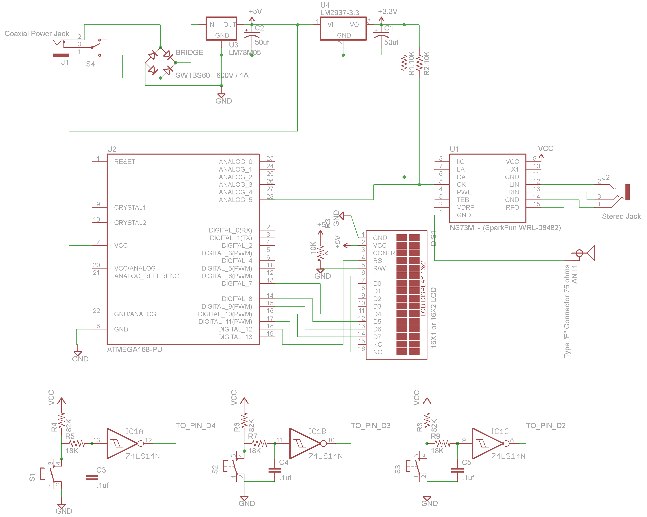
The Arduino pins are budgeted this way:
				Digital Pins -
				D12 = RS (from LCD)
				D11 = RW (NOT USED - The RW pin on the LCD is tied LOW)
				D11 = Enable (from LCD)
				D10, 9, 8, 7 = 4 data bits for LCD
				D6, 5, 4 = UP, DOWN, SET buttons

				Analog Pins:
				A4 = SDA, A5 = SCL

				There are a few pins remaining for future expansion.
Final code is in this Arduino Sketch for An FM Stereo Broadcaster. As currently configured, the NS73M transmits at 2 mw power output, with a 75 us pre-emphasis, and 100% modulation to occur at 200mV of input audio. The first time it powers up, it will start at 97.3 mhz. Afterward, the start-up frequency is whatever was previously set at the time it was powered down.
Everything is reconfigurable for other countries, including the FM Broadcast band edges (87.5 mhz to 107.9 mhz USA), and the channel spacing (200khz USA). The 4-Bit LCD interface is as follows:
LCD is being used as Write-only, so we can save a pin by tieing RW LOW and disabling RW in the LCD4bit library. Also the LCD4bit library was slightly modified to move the ENABLE pin from Arduino Pin 2 to the (now unused) Pin 11. The Two LCD4bit library changes are two lines:
int USING_RW = false; // make sure the USING_RW value is set to 'false'...

				... and Change THIS Line:
				int Enable = 2;
				TO:
				int Enable = 11;	  // making use of the now unused RW pin...
Results
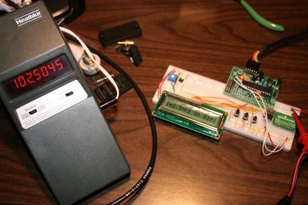
- Frequency stability is excellent – I hooked up a frequency counter and it NEVER fluctuated.
- The audio quality being transmitted is excellent – there is minimal hiss and the audio has a wide dynamic range, indicating high-quality FM modulation.
- Distance – Surprisingly, with the right audio level from an iPod nano at around 60% and a small (and legal!) antenna, it can reach my living room that is approximately 50 feet away!
- Frequency Agility has been tested across the entire US FM broadcast band, from 87.5 to 107.9, with only minor accuracy discrepancies.
- Cost – is lower than the Ramsey FM-10C ($45) when compared to the Bare-Bones Arduino ($15), the FM module ($15, Sparkfun.com), an LCD module ($5, Allelectronics.com), and some available parts (buttons, a 3.3v regulator, resistors, trimpot for LCD contrast), yet offers the same features as the Ramsey FM-25B ($139.95).
- I still have to put it in an appropriate casing.
Finishing: since this is an RF project, an enclosure should be metal. I’ve settled on a Hammond 1455N1201 extruded aluminum enclosure – they’re easy to work with and I like the style. The datasheet indicates the RF Output is 50 ohms impedance, so a BNC Connector would be suitable. Each of the separate ‘modules’ (LCD, Arduino, FM Transmitter) can be mounted to a perf board and interconnected. Breadboard power is from a 5-volt lab supply, so a 5-volt regulator (and filtering) will be added to power the Arduino and the LCD; the NS73M uses a separate 3.3-volt regulator.
FM Transmitter IC
LCD
For more detail: An FM Stereo Broadcaster PLL using Arduino