Summary of DIY Arduino 3D Laser Scanner
FabScan is an open-source DIY 3D laser scanner originally developed as a Bachelor's thesis. This guide details the process of building a custom enclosure using MDF sheets and assembling hardware components like an Arduino UNO, stepper motor, laser module, and webcam to replicate the official project. The article provides instructions for wiring, uploading specific firmware via Codebender, configuring the Ubuntu-based scanning software, and processing the resulting 3D point clouds using MeshLab.
Parts used in the FabScan DIY 3D Scanner:
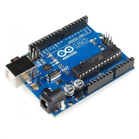
- Arduino UNO
- NEMA 17 Bipolar Stepper Motor (200 Steps)
- A4988 Stepper Motor Driver (or L298N Module)
- 5mW Red Line Laser Module
- Logitech C270 Web Camera
- 12V Power Supply (1A or 2A)
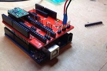
- FabScan Shield (for official build)
- MDF Wood Sheets (600mm x 300mm - 5mm thickness)
FabScan is an open-source, do-it-yourself 3D laser scanner.It started out as a Bachelor’s thesis by Francis Engelmann, supervised by René Bohne. You can find official project here.
I made my own box from MDF hood sheets and use different hardware parts.I decided to make this guide to show to you my work.
All credits for Arduino software and computer application goes to FabScan team, so thank you very much for this great open source 3D laser scanner!
Dev: Francis Engelmann Official page: hci.rwth-aachen.de/fabscan
Q & A at http://www.ardumotive.com/arduino-3d-scanner.html
Let’s get started!
P.S. Please, if you like my project vote for me. Thanks!!!! :)))
Step 1: What You Will Need
Hardware of official FabScan project:
- Arduino UNO
- A4988 Stepper Motor Driver
- FabScan-Shield – 3D Laser Scanner
- 5mW Laser Module – Red Line
- Bipolar Stepper motor – NEMA 17 (200 Steps)
- 12V – 1A power supply
- Web camera Logitech C270
To build the box you will need 4x sheets of MDF wood, size 600mm x 300mm – 5mm. You can find more info here.
Hardware that I have used:
- Arduino UNO
- Stepper motor – NEMA 17 (200 Steps)
- L298N Motor Driver Module
UPDATE: Use A4988 stepper driver - 5mW Laser Module – Red Line
- 12V – 2A power supply
- Web camera Logitech C270
I advised you to select the official FabScan hardware part list.
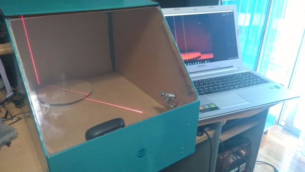
Step 2: Build the Box – Gallery of My 3D Scanner
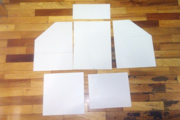
I used a Dremel cutting tool and my imagination to build my own box. This it not an easy procedure because the camera, stepper and laser module must be on the correct position to successful scan an object. If you want to make your life easier you can also buy cutted parts for only 35 euros from here.
Step 3: Hardware Connections
The connections are pretty easy:
Attach the FabScan shield on Arduino and the A4988 stepper driver on the first stepper position of it. Connect the stepper on output pins and the laser module to analog pin A4. Finally connect Power supply and usb cable. You can also find a very usufull assembly tutorial here.
Custom hardware:
If you decided to make this with my hardware parts then you have to connect the L298 stepper motor driver to Arduino pins 10,11,9,8 (you can change those pins) and laser module to Arduino pin A4. Finally connect the power supply and usb cable.
Step 4: The Code
Here’s the official FabScan code, embedded using Codebender!
Try downloading the codebender plugin and clicking on the “Run on Arduino” button to program your Arduino board with this sketch.
And that’s it, you’ve programmed your Arduino board directly from your browser!
// FabScan – http://hci.rwth-aachen.de/fabscan
//
// Created by Francis Engelmann on 7/1/11.
// Copyright 2011 Media Computing Group, RWTH Aachen University. All rights reserved.
//
// Chngelog:
// R. Bohne 29.01.2013: changed pin mapping to Watterott FabScan Arduino Shield
// R. Bohne 30.12.2013: added pin definitions for stepper 4 –> this firmware supports the new FabScan Shield V1.1, minor syntax changes. Steppers are now disabled at startup.
// R. Bohne 12.03.2014: renamed the pins 14..19 to A0..A5 (better abstraction for people who use Arduino MEGA, etc.)
define LIGHT_PIN A3
define LASER_PIN A4
define MS_PIN A5
//Stepper 1 as labeled on Shield, Turntable
define ENABLE_PIN_0 2
define STEP_PIN_0 3
define DIR_PIN_0 4
//Stepper 2, Laser Stepper
define ENABLE_PIN_1 5
define STEP_PIN_1 6
define DIR_PIN_1 7
//Stepper 3, currently unused
define ENABLE_PIN_2 11
define STEP_PIN_2 12
define DIR_PIN_2 13
//Stepper 4, currently unused
define ENABLE_PIN_3 A0
define STEP_PIN_3 A1
define DIR_PIN_3 A2
define TURN_LASER_OFF 200
define TURN_LASER_ON 201
define PERFORM_STEP 202
define SET_DIRECTION_CW 203
define SET_DIRECTION_CCW 204
define TURN_STEPPER_ON 205
define TURN_STEPPER_OFF 206
define TURN_LIGHT_ON 207
define TURN_LIGHT_OFF 208
define ROTATE_LASER 209
define FABSCAN_PING 210
define FABSCAN_PONG 211
define SELECT_STEPPER 212
define LASER_STEPPER 11
define TURNTABLE_STEPPER 10
//the protocol: we send one byte to define the action what to do.
//If the action is unary (like turnung off the light) we only need one byte so we are fine.
//If we want to tell the stepper to turn, a second byte is used to specify the number of steps.
//These second bytes are defined here below.
define ACTION_BYTE 1 //normal byte, first of new action
define LIGHT_INTENSITY 2
define TURN_TABLE_STEPS 3
define LASER1_STEPS 4
define LASER2_STEPS 5
define LASER_ROTATION 6
define STEPPER_ID 7
int incomingByte = 0;
int byteType = 1;
int currStepper;
//current motor: turn a single step
void step()
{
if(currStepper == TURNTABLE_STEPPER){
digitalWrite(STEP_PIN_0, LOW);
}else if(currStepper == LASER_STEPPER){
digitalWrite(STEP_PIN_1, LOW);
}
delay(3);
if(currStepper == TURNTABLE_STEPPER){
digitalWrite(STEP_PIN_0, HIGH);
}else if(currStepper == LASER_STEPPER){
digitalWrite(STEP_PIN_1, HIGH);
}
delay(3);
}
//step the current motor for times
void step(int count)
{
for(int i=0; i<count; i++){
step();
}
}
void setup()
{
// initialize the serial port
Serial.begin(9600);
pinMode(LASER_PIN, OUTPUT);
pinMode(LIGHT_PIN, OUTPUT);
pinMode(MS_PIN, OUTPUT);
digitalWrite(MS_PIN, HIGH); //HIGH for 16microstepping, LOW for no microstepping
pinMode(ENABLE_PIN_0, OUTPUT);
pinMode(DIR_PIN_0, OUTPUT);
pinMode(STEP_PIN_0, OUTPUT);
pinMode(ENABLE_PIN_1, OUTPUT);
pinMode(DIR_PIN_1, OUTPUT);
pinMode(STEP_PIN_1, OUTPUT);
pinMode(ENABLE_PIN_2, OUTPUT);
pinMode(DIR_PIN_2, OUTPUT);
pinMode(STEP_PIN_2, OUTPUT);
pinMode(ENABLE_PIN_3, OUTPUT);
pinMode(DIR_PIN_3, OUTPUT);
pinMode(STEP_PIN_3, OUTPUT);
//disable all steppers at startup
digitalWrite(ENABLE_PIN_0, HIGH); //HIGH to turn off
digitalWrite(ENABLE_PIN_1, HIGH); //HIGH to turn off
digitalWrite(ENABLE_PIN_2, HIGH); //LOW to turn on
digitalWrite(ENABLE_PIN_3, HIGH); //LOW to turn on
digitalWrite(LIGHT_PIN, LOW); //turn light off
digitalWrite(LASER_PIN, HIGH); //turn laser on
Serial.write(FABSCAN_PONG); //send a pong back to the computer so we know setup is done and that we are actually dealing with a FabScan
currStepper = TURNTABLE_STEPPER; //turntable is default stepper
}
void loop()
{
if(Serial.available() > 0){
incomingByte = Serial.read();

switch(byteType){
  case ACTION_BYTE:

      switch(incomingByte){    //this switch always handles the first byte
        //Laser
        case TURN_LASER_OFF:
          digitalWrite(LASER_PIN, LOW);    // turn the LASER off
          break;
        case TURN_LASER_ON:
          digitalWrite(LASER_PIN, HIGH);   // turn the LASER on
          break;
        case ROTATE_LASER: //unused
          byteType = LASER_ROTATION;
          break;
        //TurnTable
        case PERFORM_STEP:
          byteType = TURN_TABLE_STEPS;
          break;
        case SET_DIRECTION_CW:
          if(currStepper == TURNTABLE_STEPPER){
            digitalWrite(DIR_PIN_0, HIGH);
          }else if(currStepper == LASER_STEPPER){
            digitalWrite(DIR_PIN_1, HIGH);
          }
          break;
        case SET_DIRECTION_CCW:
          if(currStepper == TURNTABLE_STEPPER){
            digitalWrite(DIR_PIN_0, LOW);
          }else if(currStepper == LASER_STEPPER){
            digitalWrite(DIR_PIN_1, LOW);
          }
          break;
        case TURN_STEPPER_ON:
          if(currStepper == TURNTABLE_STEPPER){
            digitalWrite(ENABLE_PIN_0, LOW);
          }else if(currStepper == LASER_STEPPER){
            digitalWrite(ENABLE_PIN_1, LOW);
          }
          break;
        case TURN_STEPPER_OFF:
          if(currStepper == TURNTABLE_STEPPER){
            digitalWrite(ENABLE_PIN_0, HIGH);
          }else if(currStepper == LASER_STEPPER){
            digitalWrite(ENABLE_PIN_1, HIGH);
          }
          break;
        case TURN_LIGHT_ON:
          byteType = LIGHT_INTENSITY;
          break;
        case TURN_LIGHT_OFF:
          digitalWrite(LIGHT_PIN, LOW);
          break;
        case FABSCAN_PING:
          delay(1);
          Serial.write(FABSCAN_PONG);
          break;
        case SELECT_STEPPER:
          byteType = STEPPER_ID;
          break;
        }

      break;
   case LIGHT_INTENSITY:       //after this point we take care of the second byte if one is sent
      analogWrite(LIGHT_PIN, incomingByte);
      byteType = ACTION_BYTE;  //reset byteType
      break;
    case TURN_TABLE_STEPS:
      step(incomingByte);
      byteType = ACTION_BYTE;
      break;
    case STEPPER_ID:
      Serial.write(incomingByte);
      currStepper = incomingByte;
      byteType = ACTION_BYTE;
      break;
}(https://codebender.cc/sketch:186175)
If you decided to make this with my hardware parts, click the Edit button and:
- Add lines
#include
const int stepsPerRevolution = 200; // change this to fit the number of steps per revolution
// for your motor
Stepper myStepper(stepsPerRevolution, 10, 11,8,9); - Replace step() function with:
void step() {
myStepper.setSpeed(1);
myStepper.step(1);
}
Step 5: Software (computer Side)
We will use the “FabScan Ubuntu Live DVD” image that was created by Mario Lukas. You can download it from here, this image has preinstalled the FabScan software. You can write the image on a flash drive with Win32DiskImager (download link) and use it without installing linux os on your system.You can find more options for other operating systems here.
Important note! If you use the “Try Ubuntu” option make sure to save your files before shutdown the computer!
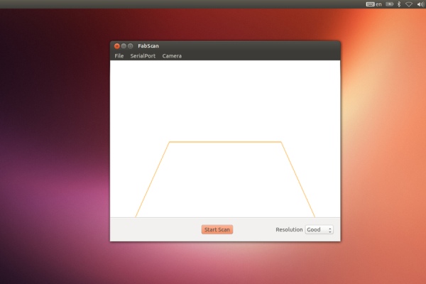
See the above images and follow the steps:
- Select SerialPort
- Select Camera
- File – Control Panel
- Click on detect laser (don’t put any object in scanner yet) and select ‘enable’
- Click on “Fetch Frame” and make sure that the blue horizontal line touches the top of the turning table and the yellow horizontal line touches the bottom of the turning table. Also the yellow vertical line should pass through the center of the turntable. A non aligned camera will result in distorted scans!
After setup close control panel window, put an object inside scanner and press the start scan button.
Tip: You can change the configuration.xml file of FabScan by following this guide.
Saving 3D image:
When scanning procedure is completed you can save the scanned 3D object as an 3D pointcloud .pcd or .ply file. You can also save it as an 3D stl file but this doesn’t work to all platforms. If you would like you can also open an older scanned object by selecting File – OpenPointCloud.
What next?
You can use MeshLab for processing scanned object and then print it with a 3D printer!
File processing with MeshLab:
1. Make sure that you saved object as an .ply file.
2. Open file with MeshLab
3. In MeshLab, compute the normals (Filters/Point Set/Compute normals for point sets)
4. Then reconstruct the surface using poisson reconstruction (Filters/Point Set/Surface Reconstruction: Poisson)
The end 😀
Many many thanks to FabScan team!!!
Source: DIY Arduino 3D Laser Scanner
- What software is required to run the FabScan computer side?
You must use the "FabScan Ubuntu Live DVD" image which has preinstalled the FabScan software. - How do you program the Arduino board?
The code can be embedded using Codebender, allowing you to program the board directly from your browser. - Can I use a different motor driver than the official one?
Yes, you can use an L298N Motor Driver Module instead of the A4988, though the A4988 is recommended. - What file formats can be saved after scanning?
You can save the scanned object as a .pcd, .ply, or .stl file, though .stl may not work on all platforms. - How do you align the camera for accurate scans?
The blue horizontal line must touch the top of the turntable, the yellow line the bottom, and the yellow vertical line must pass through the center. - Which tool is recommended for building the box?
A Dremel cutting tool was used to cut the MDF wood sheets for the enclosure. - What is the best way to process the scanned object data?
You should use MeshLab to compute normals and reconstruct the surface using Poisson reconstruction. - Does the official code support microstepping?
Yes, the setup initializes MS_PIN to HIGH for 16 microstepping or LOW for no microstepping.