
Summary of Arduino stepper motor and servos shield
This article guides users in constructing a custom Arduino shield designed to control three servos and one stepper motor via four potentiometers. The process involves etching or milling a single-sided PCB, drilling component holes, optional laser engraving for text and shape, and final board shaping using tools like a disc sander. Essential components include terminal blocks, stackable headers, a chip socket, an L293D motor driver, and standard soldering equipment.
Parts used in the Arduino Servo and Stepper Motor Shield:
- 7 x 3 pin 3.5mm terminal blocks
- 2 x 2 pin 3.5mm terminal blocks
- 2 x 8 pin stackable headers
- 2 x 6 pin stackable headers
- 1 x 8 pin chip socket
- 1 x L293D motor driver chip
- Soldering iron
- Solder
This instructable will show you show to build an Arduino shield which can be used to control 3 servos and 1 stepper motor using 4 potentiometers. You will need:
access to a laser printer/cnc router/etching chemicals
7 x 3 pin 3.5mm terminal blocks
2 x 2 pin 3.5mm terminal blocks
2 x 8 pin stackable headers
2 x 6 pin stackable headers
1 x 8 pin chip socket
1 x L293D motor driver chip
optional: access to a laser cutter
soldering iron
solder
something to shape the board, eg disc sander
Step 1: Etch the Board
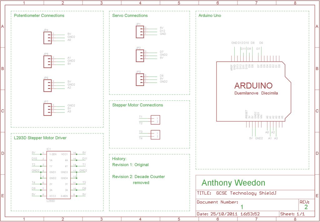
 GCSE Technology Shield.sch
Step 2: Drill the Board
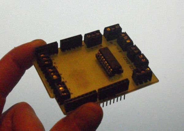
The next step is to carefully drill the holes for the components. Below is a picture of the drilled board. Drilling before shaping means we can align the board for laser engraving.
Step 3: Laser Etch the board
This step is optional, but provides the shape of the board and some useful text on the top of the board. Below is the 2D design file, and also a DXF. The hardest part of all of this project is lining up the laser. I drew a line along the line of the holes that you should have drilled, and used the laser cutter to follow the path without cutting, so I could see if it was in the right place. When you are happy, engrave the writing onto the surface of the board (I could recommend testing the settings on an old PCB).
Step 4: Shape the Board
You should now have an outline engraved onto the top of the board. As the picture in the previous step shows, either disk-sand the edges, or use some other method, but shape the board to the outline. I used a small drill bit cutting disk for the finer details.
optional: access to a laser cutter
soldering iron
For more detail: Arduino stepper motor and servos shield
- What is the primary function of this project?
The project builds an Arduino shield to control 3 servos and 1 stepper motor using 4 potentiometers. - How do I prepare the PCB before drilling?
You must access a laser printer, CNC router, or etching chemicals to create the board from provided Eagle files. - Why should I drill the board before shaping it?
Drilling before shaping allows you to align the board correctly for laser engraving. - Is laser engraving mandatory for this build?
No, laser etching the board is optional but provides the shape outline and useful text on the surface. - What tools can be used to shape the board edges?
You can use a disc sander or a small drill bit cutting disk for finer details. - Which specific motor driver chip is required?
The project requires exactly one L293D motor driver chip. - How many stackable headers are needed for the assembly?
You need two 8-pin stackable headers and two 6-pin stackable headers. - What software files are provided for the schematic?
The article provides GCSE Technology Shield.sch and GCSE Technology Shield.brd files.