
Summary of My Arduino Ping Display Robot
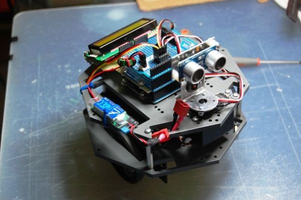
This article details the construction of an Arduino-based obstacle-avoiding robot named "Ping Boat." The project utilizes a Ping))) ultrasonic sensor to detect obstacles and displays the measured distance on an LCD screen. Designed for beginners with electronics knowledge, the build emphasizes custom servo and LCD shields to minimize wiring complexity and improve portability compared to breadboard setups.
Parts used in the Ping Boat:
- Arduino UNO or compatible
- OCTAGON GioBlu Robotics Module or other frame
- Ping))) Parallax mounting bracket kit
- Two 360-degree rotation servo motors (HSR-1425SCR)
- Two 6 cm rubber no-slip wheels
- Standard servo for Ping mounting (optional)
- Two Gioblu Robotics servo brackets
- Four 4 cm PCB spacers
- Two protoschields for servos, battery, and display
- One 16x2 HD44780 compatible LCD Display
- One potentiometer
- Nine-volt battery holder
- 2s Lipo 1200mAh 7.4 v battery
- UBEC 5.4 / 6V power regulator
- Pivot wheel
- Matrix board piece for display shield
- Strips for shield assembly
Goals
Hello all.
I hope to please share a little robot that I have just finished building.
There are many Ping Boat, perhaps with a tutorials and display less so without pretension, will illustrate what I could do.
I gave myself the goal of realizing a robot that avoids obstacles, hence the use of Ping, who had more autonomy (and less hassle to reload always stylus) and displayed on a LCD display the distance measured obstacle.
The tutorial is directed for beginners but with knowledge of electronics and Arduino programming.
Step 1: List of Materials
1 – Arduino UNO or compatible
2 – Module OCTAGON GioBlu Robotics http://www.gioblu.com/prodotti?page=shop.product_details&flypage=flypage_images.tpl&product_id=136&category_id=60 or other frame
1 – Ping))) Parallax mounting bracket kit http://www.parallax.com/Store/Robots/AllRobots/tabid/755/ProductID/248/List/0/Default.aspx?SortField=ProductName,ProductName
2 – Servo motors with 360 rotation , in my case HSR-1425SCR
2 – 6 cm wheels with rubber no-slip
1 – std servo for the Ping (in my case is not required but can be implemented)
2 – servo brackets Gioblu Robotics http://www.gioblu.com/prodotti?page=shop.product_details&flypage=flypage.tpl&product_id=78&category_id=34
4 – PCB spacers from 4 cm http://http://www.robot-italy.com/product_info.php?cPath=7_135&products_id=1189
2 – protoschield for servos, battery and display and added http://www.robot-italy.com/product_info.php?products_id=879(or other sites)
1 – 16×2 HD44780 compatible LCD Display http://www.robot-italy.com/product_info.php?cPath=59_194&products_id=237
1- potentiometer
1 – 9v battery holder
1 – 2s Lipo 1200mAh 7.4 v
1 – UBEC 5.4 / 6V http://www.cnchelicopter.com/servlet/the-1528/hobbywing-UBEC-dsh-3A-(2-dsh-6S-Lipo/Detail
1 – pivot wheel
1 – piece of matrix board for the display shield
– some strip for shield
– some screw patience and passion..
Step 2: SERVO SHIELD CONSTRUCTION
First we begin by shield, why I have chosen this path?. When you need to connect several servo motors, a sensor, batteries etc, of course, there are several PIN signals, power supply and ground to use.
Normally the various little robots are joined by a breadboard to allow you to manage everything at the expense of a lot of threads around that maybe every time you disconnect and still always give a feeling of chaos.
A shield to be attached to Arduino simplifies everything and makes it more convenient connections. As you know for the servos or motors there are already on the market different and functional, eg one or dell’Adafruit or SparkFun, in any case the realization in the house is very simple and inexpensive.
As you can see from the first two photos are soldered several rows of three legs (I have made ââ6, but you can add several more), each leg corresponds to the three poles of the servo and the sensor (signal, 5v, gnd -white/red/black or yellow/red/back). Then sold in parallel (third photo) the 5v (center pin) and GND (pictured blue wire) and the latter connected to the power connector, so all you will connect to the row of pins will be powered together.
For the signal pin, you can decide if you knew at the start (as in my case) corresponds to which pin, solder a wire directly to the corresponding pin, or if you want to manage it from time to time just add (second photo), a row of strip females to connect with a wire to the desired pin. In the above I added a reset button and a LED connected to pin 13 directly to Arduino board.
Step 3: LCD SHIELD CONSTRUCTION
Skipping of course, as you will find dozens of tutorials on how to connect one display to Arduino board eg
http://arduino.cc/en/Tutorial/LiquidCrystal
but I repeat, if you want to take the opportunity to enter into the project, which necessary to reduce the number of wires around that in this case are several, so we can again make a shield that can be useful for other projects with the Arduino.
Of the 16 pins of a display, only 12 are needed for our purpose.
If you look at the first and third photo should crop a breadboard that will serve us well as a support for the display, and like a “bridge” connecting to the Arduino pins.
So what should we do, sold (I have soldered slightly inclined, as shown in picture 2, in order to better read the display) a female strip of 16 feet to the matrix board, make from each pin that is used (see the tables below) a wire soldered directly to the corresponding pin of Protoshield, then we’re going to overlap to the Arduino board and above this shield (last photo) will get that one made for the servo and sensor with zero visible wires.
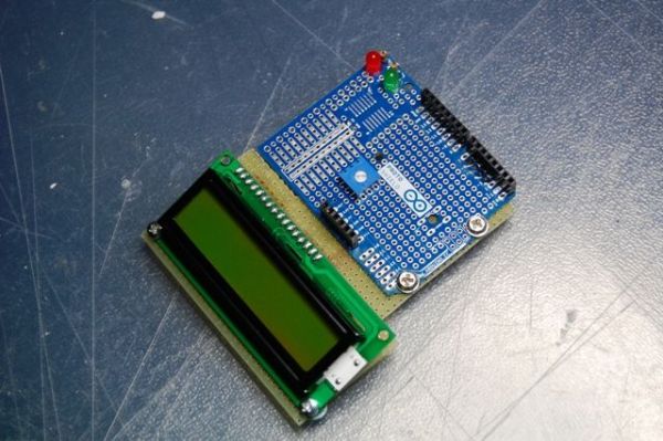
The last photo is the display in operation.
Step 4: TABLE FOR THE CONNECTIONS
| PIN | connect to | |||||
| 1 | GND | |||||
| 2 | 5V | |||||
| 3 | (Central Pin of the POT – Add to this one wire to 5v and one to GND) | |||||
| 4 (RS) | 3 | |||||
| 5 (RW) | GND | |||||
| 6 (EN) | 4 | |||||
| 11(DB4) | 5 | |||||
| 12(DB5) | 6 | |||||
| 13(DB6) | 11 | |||||
| 14(DB7) | 12 | |||||
| 15 | 5V | |||||
| 16 | GND | |||||
| Ping Servo Signal Pin 10 | ||||||
| Led to Pin 13 | ||||||
| Ping Sensor Signal Pin 7 | ||||||
| DX Wheel Pin 9 | ||||||
| SX Wheel sx Pin 8 | ||||||
Put the display power under servo shield so it is managed by a battery’s capacity.
2 – Module OCTAGON GioBlu Robotics
1 – Ping))) Parallax mounting bracket kit
2 – Servo motors with 360 rotation , in my case HSR-1425SCR
For more detail: My Arduino Ping Display Robot
- What is the primary goal of this robot project?
The goal is to create a robot that avoids obstacles using a Ping sensor and displays the measured distance on an LCD. - Can beginners build this robot?
Yes, the tutorial is directed for beginners who possess knowledge of electronics and Arduino programming. - Why did the author choose to build custom shields?
Custom shields simplify connections between multiple servos, sensors, and batteries while reducing the chaos of loose threads found on breadboards. - How many pins are required for the LCD display in this project?
Only 12 of the 16 pins on the display are needed for this specific purpose. - Which pin controls the Ping Sensor Signal?
The Ping Sensor Signal Pin is connected to Pin 7 on the Arduino. - What type of battery is used to power the system?
A 2s Lipo 1200mAh 7.4 v battery is used, regulated by a UBEC 5.4 / 6V unit. - How are the servo motors connected in the custom shield?
Soldered rows of three legs correspond to the signal, 5v, and gnd poles of each servo and sensor. - Does the project require a standard servo for the Ping sensor?
No, it is not strictly required but can be implemented if desired.