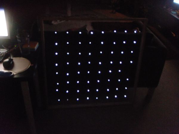
For a party we were about to have I wanted a cool light display to use with my new Xmas present – an Arduino Uno. Having looked at the LED matrix’s here I wanted a bigger one that I could hang on the balcony.
I also wanted it to interact with music and flash at different sound levels and have a keypad to select which animation to run.
Thus I came up with this one using some spare Xmas lights I had already butchered for some outside art projects. I also wanted it to look arty, hence the use of copper wire for inside the frame.
Before we start on the construction I will go through some of the theory behind the matrix.
Please Note : I didn’t use resistors between the matrix connecting wires and the Arduino. You should really use them to limit the current to the LED’s and also avoid damaging the Arduino. If you don’t use them then that’s at your own risk
Step 1: Materials Required
As stated this is a 8×8 matrix so you will need 64 LEDS. I had some spare 25 LED xmas light strings, so I used these as my source for the LEDS.
Timber for making the frame. This frame used approx 3.6m of 45mmx18mm of timber.
Arduino Uno
Power Supply (I used a 9v battery)
Copper Wire for the wiring inside the frame. This copper wire has a coating on it which is not conductive so is ideal for this. The type used in motor windings is ideal. I got this from the local metal scrapman. Need about 19m of this. The thicker the wire the better.
Cat 5 (network) cabling so the matrix pins can be connected to the microcontroller.
Screws and/or wood glue to build the frame.
Keypad, Microphone, Resistors, Capacitor’s and op-amps required for the hardware add-ons. Please see those steps for the links to the other instructables that list the required components.
Tools Required
Saw for cutting the timber
Staple gun for attaching the copper wire to the frame
Soldering Iron and solder
Multimeter
Pliers
Electric Drill + drill bits
Computer to program the Arduino along with the correct USB cable.
Sharp knife – Stanley knife or similar.
Step 2: Theory of operation
Trying to light up 64 LEDS in an controlled manner such that you can turn on individual LED’s to create shapes or animations, would normally require all 64 LEDS’s to be connected individually to some kind of controller.
The Arduino Uno only has 18 connections (pins) that can be utilised for this type of behaviour. Therefore no good for this type of application. But that can be changed by multiplexing the LED’s connection using a matrix.
What is this you ask. Well its a method of connecting a large number of LED’s to a controller with a limited number of pins. For this project we would only need 16 pins on the microcontroller to control the 64 LEDS.
Please note that the explanation below are meant in their basic terms without getting to technical.
First we need to understand how LEDS work. LEDS are basically diodes. i.e. they only allow voltage to flow in one direction. If were to connect a diode and a light bulb to a battery then the bulb will light if the diode is used in the right direction. If reversed then the bulb will not light. Same with a LED (light emitting diode). If connect directly to a 3v battery then it will only light when connected the right way round. That is the anode (longest lead) being connected to the + of the battery and the cathode (shortest lead) connected to the – of the battery. This is important for the operation of the matrix.
Therefore we can use this theory of LED’s in the matrix below. If we connect Col 1 to ground and Row 1 to a + voltage then the LED where these two lines meet will light up. No other LED’s will light up due to no voltage flowing to them. If we reverse the voltage on just one of the lines then that LED will turn off.
If you want two LED’s to appear to be on then you turn the first one on and then off. Then really quickly you turn the other one one on and off. If you repeat this cycle really fast then to the person watching they will appear to both be on. This is called persistence of vision (http://en.wikipedia.org/wiki/Persistence_of_vision ) and is very useful for these type of projects.
Using this theory means that we only need 16 input pins on the Arduino rather then then the 64 pins to drive each LED.
Step 3: Constructing the frame.
As the matrix is 8 LED’s wide and 8 LED’s high I made the frame to make each LED be 100mm apart in both directions. I also wanted the thicker part of the timber to be the side that I threaded the copper wire through. Use the wood in any orientation you require but change the lengths below to suit.
Hence I needed a frame that would be 900mm x 900mm on the inside measurements. Hence I cut two pieces of the timber to be 900mm wide and another two to be 900mm+ thickness of the timber wide). In my case the thickness is 18mm so the timber should be 936mm long.
I then measured and marked every 100mm along the shortest timber pieces so I knew where to drill the holes to thread the copper wire through.
For the longer pieces you need to the same, but don’t forget to start measuring at 18mm in from one end. This is to take into account the construction of the frame. This part can also be done once the frame is constructed.
Once the holes are marked then drill a hole in each one. Select a drill bit just larger then the diameter of the copper wire you are using. Sand the holes drilled so everything is smooth and no sharp edges exist.
Then you need to put the frame together. I just screwed and glued the frame where they met. Don’t forget to make the shorter pieces the inside pieces of the frame. See the sketch to see what I mean.
I then sanded the frame so make it all smooth and get rid of the pencil marks I had made on it. You could paint or stain it at this point if you want to make it look nicer. I didn’t and wish I had. But I can remove the copper wires fairly easily and do it later if I really wanted to.
Arduino Uno
Power Supply (I used a 9v battery)
For more detail: 8×8 LED Matrix Animations using an Arduino