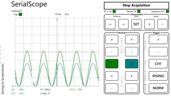
In this guide I will explain how to use a Windows 8.1 phone, Arduino Uno board, and HC-05 Bluetooth module to build a wireless oscilloscope. The phone application has the critical functions of an oscilloscope, although the bandwidth is a measly 300 Hz. Still, if you want to see squiggly lines on your phone, it is a fun project.
Today’s phones have the ability to perform real-time signal processing. The challenge is getting the data into the phone and sourcing a low-cost front end. The Arduino Uno performs the data acquisition and packaging. It sends the data, using rfcomm, over the HC-05 Bluetooth module to the phone. The phone runs an application called “SerialScope” that unpacks the data and plots it.
Step 1: Components and Wiring
Parts
I have tested this guide with the following components:
- Nokia 1520 phone with Windows Phone 8.1
- HC-05 Bluetooth module
- Arduino Uno R3
- Arduino IDE 1.6.1
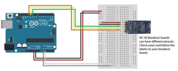
Wiring
- HC-05 GND — Arduino GND Pin
- HC-05 VCC (5V) — Arduino 5V
- HC-05 TX — Arduino Pin 10 (soft RX)
- HC-05 RX — Arduino Pin11 (soft TX)
- A0 — Analog in for channel 1
- A1 — Analog in for channel 2
Without any conditioning the input to the ‘scope is limited to 0-5V. It also doesn’t include any anti-aliasing filters so that can be a problem if you are doing any serious analysis.
Step 2: Program the HC-05
The HC-05 needs to be programmed to transmit at 115,200 baud. There is an Instructable at: http://www.instructables.com/id/Modify-The-HC-05-B… that shows how to do this. The only thing I found missing in the Instructable is that if you’re using Arduino’s serial monitor make sure you select “Both NL and CR” on the drop down.
None of the other parameters of the HC-05 need to be modified.
Step 3: Download the MinSegBus library for the Arduino
In order to send data over a serial link, it is wrapped in a data frame. This frame includes a CRC and an address byte that is used to verify no frames are dropped.
The data bus library is called MinSegBus and is available on a public repository on GitHub:
https://github.com/MoreCoffee12/MinSegBus
You can fork this repository and use the code that way or use the attachment to this step. The GitHub will always have the latest version so that’s the preferred method. Either way, you will need to add the library to your Arduino IDE (see http://www.arduino.cc/en/guide/libraries for details).
Step 4: Program the Arduino
To get accurate samples, the timer interrupts are used on the Arduino so this program structure might look a little different from other Arduino programs you have worked on. This Instructable has a lot more details on the Arduino timers, if you are interested: http://www.instructables.com/id/Arduino-Timer-Inte…
The code can be downloaded from GitHub (https://github.com/MoreCoffee12/SerialScope/tree/m…), the .zip file attached to this step, or typed in from below.
// Firmware to capture 2-channels of data and send it out over BlueTooth.
// This implementation is designed to provide data to the Windows Phone 8
// Application
//
// Software is distributed under the MIT License, see ArduinoFirmware_License.txt
// for more details.
// This library provides a frame structure
// for the data.
#include <minsegbus.h>
MinSegBus mbus;
// The SoftwareSerial library is used to provide
// data to the Bluetooth module.
#include <SoftwareSerial.h>
SoftwareSerial BTSerial(10, 11); // RX | TX
#define maxbuffer 0x0400
#define ADCChannels 0x0002
//storage variables
boolean toggle0 = 0;
// Define the ADC
int analogPinCh1 = 0;
int analogPinCh2 = 1;
bool bOutput;
// Buffers
unsigned short iUnsignedShortArray[ADCChannels*2];
unsigned char cBuff[maxbuffer];
// MinSegBus vaiiables
unsigned char iAddress;
unsigned short iUnsignedShort;
unsigned int iBytesReturned;
unsigned int iErrorCount;
unsigned int iIdx;
void setup()
{
// Serial port setup
Serial.begin(115200);
BTSerial.begin(115200);
// Definitions for the MinSegBus
iAddress = 0x000;
// Tattle tale pins, used to confirm timing
pinMode(9, OUTPUT);
// Get two samples before sending the frame
bOutput = false;
// Timer setup. Begin by disabling the interrupts
// Reference: http://www.instructables.com/id/Arduino-Timer-Interrupts/?ALLSTEPS
cli();
// Timer control registers
TCCR0A = 0; // Set entire TCCR0A register to 0
TCCR0B = 0; // Same for TCCR0B
// Set compare match register for 625Hz increment
OCR0A = 99; // = (16*10^6) / (500*256) – 1 (must be < 256)
// Turn on the CTC mode
TCCR0A |= (1 << WGM01);
// Set CS01 and CS00 bits for 256 prescaler
TCCR0B |= (1 << CS02 );
// Enable the timer compare interrupt
TIMSK0 |= ( 1 << OCIE0A );
// enable interrupts
sei();
}
// All the work is done in the timer interrupt service routine (ISR)
void loop()
{
return;
}
// Timer0 interrupt 1kHz. This also toggles pin 31
// to provide a method to veriy the sampling frequency.
ISR(TIMER0_COMPA_vect){
if (toggle0)
{
digitalWrite(9,HIGH);
toggle0 = 0;
}
else
{
digitalWrite(9,LOW);
toggle0 = 1;
}
if( bOutput)
{
iUnsignedShortArray[2] = analogRead(analogPinCh1);
iUnsignedShortArray[3] = analogRead(analogPinCh2);
iBytesReturned = 0;
iAddress++;
mbus.ToByteArray(iAddress, iUnsignedShortArray, ADCChannels*2, maxbuffer, &cBuff[0], &iBytesReturned);
bOutput = false;
}
else
{
iUnsignedShortArray[0] = analogRead(analogPinCh1);
iUnsignedShortArray[1] = analogRead(analogPinCh2);
bOutput = true;
for (iIdx = 0; iIdx<iBytesReturned; iIdx++)
{
// Uncomment this line to write to the serial port. Useful
// only for debugging
//Serial.write(cBuff[iIdx]);
BTSerial.write(cBuff[iIdx]);
}
}}
For more detail: Wireless Arduino Oscilloscope