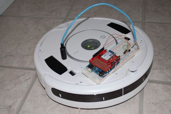
I wanted to see if I could operate my Roomba remotely and get it to report its status via Twitter while I was away from home. I also wanted to make the device independent of a computer. This is the solution I came up with and it works very well.
Follow @TheRoomba on Twitter to see what mine is doing!
Step 1: Needed Parts and Tools
Parts:
- 1x – Small signal, low power PNP transistor (I used a 2N2907A (may also be known as NTE159))
- 1x – 8-Pin mini DIN male connector
- 1x – 7805 5V voltage regulator
- 1x – Solderless breadboard
- 1x – Arduino board
- 1x – Sparkfun WiFly Arduino shield
- Row of five or more male pin headers
- A short piece of Cat5 cable or similar wire (Cat5 is 24 AWG)
- And last but certainly not least, a Roomba*
Tools:
- Soldering iron
- Small scissors
- Third hand
- Hot glue gun
- Multimeter
Assumptions:
- For the purpose of this Instructable, I am going to be assuming that you have a basic knowledge of basic electronics, the Arduino and the Arduino’s programming language.
*I have only tested this with the 500 Series. However, it should work with newer models, but I am not sure about older models.
Step 2: Roomba’s Serial Connector
All 500 series Roombas have a serial connector on them. We will be using this serial port to control and read sensor data from the Roomba. The serial connector is simply an 7-pin Mini-DIN jack with the block in the center. You can usually purchase these for a few dollars at your local electronics store.
To access the serial connector: remove the bin, gently pull up on the back edge of the top plate until the two clips in the back release. Now, use a flat blade screwdriver to gently pry up the rest of the plate. The connector is to the right of the control buttons.
You may wish to drill a hole in the plate to access the port without the plate removed.
Step 3: Creating a Connection Cable
The easiest way to connect to the serial port is to create a short cable using an 8-Pin mini DIN connector, some male pin headers and a short length of Cat5 cable. You may use a 7-Pin mini DIN instead if it has the plastic block in the center and not the bottom as the center pin is not connected. Strip a small amount of insulation off of the individual wires. If you don’t have a wire stripper that can strip wires this small, gently rotate a pair of scissors around the insulation and pull it off.
It may be tricky to solder the wires into the small cups of the mini DIN connector. Use your Third Hand to hold the wire and mini DIN connector. You may wish to place the wire between a small piece of folded paper to prevent teeth marks from the Third Hand. Work form the inside out. If the wire is soldered in the cup properly, you can use a solder vacuum to clean up an excess solder on the exterior of the cup. Make a chart of what cup you attached each wire to.
Use a multimeter to check for shorts between pins.
The pins may be bent slightly out of place. Insert the pins into the Roomba’s connector to realign them.
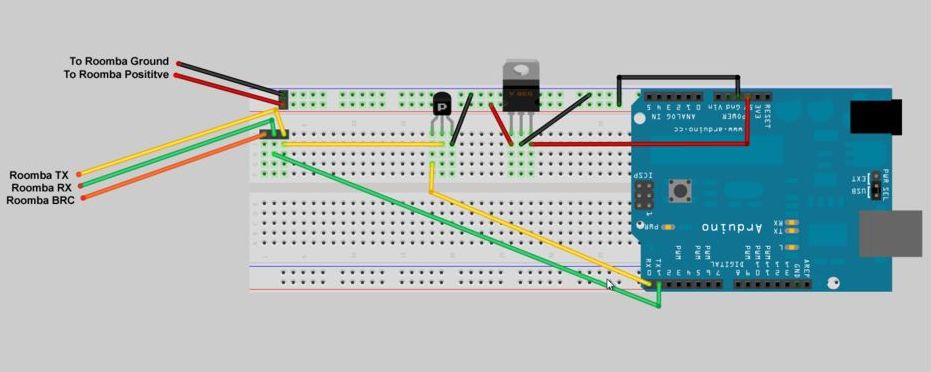
Use some hot melt glue between each wire so the do not bend and short against each other. Wrap some tape around all the wires to prevent shorts against the case. Reassemble the mini DIN connector, but do NOT slide the outer case of the mini Din over the pins until functionality has been verified. This will make it easier to modify if necessary. Strip the other end of the wire. Pins 6 and 7 (see image below) are both ground; attach them to the same pin header. Pins 1 and 2 are both positive. The voltage on these pins varies. When docked, it is about 20V, otherwise it is the voltage of the battery (about 14V). Attach them both to the same header. Attach the rest of the wires to their own headers.
- 1x – Small signal, low power PNP transistor
- 1x – 8-Pin mini DIN male connector
- 1x – 7805 5V voltage regulator
For more detail: Web-controlled Twittering Roomba using an Arduino