Summary of RGB LED Rainbow Fader using an Arduino
This article details the construction of a "RainBoard," an RGB LED rainbow fader controlled by an Arduino Uno. Using only three digital pins, it manages 45 RGB LED channels via shift registers and pulse-width modulation (PWM). The project involves soldering headers to LED strips, wiring six 74HC595 shift registers and six ULN2803 Darlington drivers to control brightness and color transitions. The build requires basic tools like a soldering iron and breadboards, aiming for a setup time under 30 minutes.
Parts used in the RainBoard:
- 2x RGB LED Strip - 30 LED/m 1m
- 2x Break Away Headers - Straight
- 6-8x 74HC595 8-Bit Shift Registers
- 6-8x ULN2803 DIP 8-Channel Darington Driver
- 2x Basic Breadboard
- 1x Arduino Uno (or other similar model)
- 1x 12VDC Wall Adapter Power Supply
- 1x Any way to connect things together (jumper wires or 22 gauge wire)
- 1x Soldering Iron
- 1x Third Hand (optional)
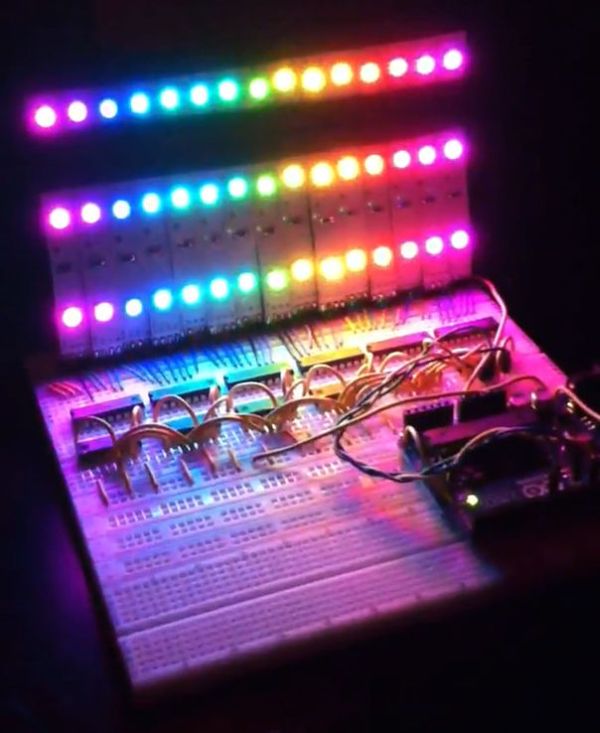
Introducing the RainBoard: A simple RGB LED Rainbow fader using an Arduino Uno and a few simple components. Believe it or not, we will control 45-channels of RGB LEDs at 32 brightness levels using only 3 digital pins from the Arduino! How is this possible you ask? By using two magic concepts: Shift Registers, and Pulse-Width Modulation. Some of the schematics/images may seem daunting, but if all instructions are followed carefully, it should be easy to have this set up and running in less than 30 minutes (perfect for those that forgot to get that special someone a Christmas present this year!).
This is my entry into the Make it Glow Contest. And also my very first Instructable, I hope you like it!
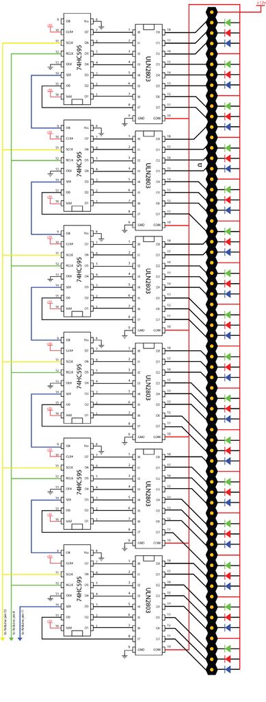
Here’s the schematic and the diagram of what we will be making.
Step 1: Parts
2x RGB LED Strip – 30 LED/m 1m
We need these to make the pretty rainbow effect! One of the most crucial components as you can’t make it glow if you don’t have something to emit light. We need two because each strip will be cut into 10 sections and we need 15 sections total for our project. This will give us 5 sections as spares in case something goes wrong.
2x Break Away Headers – Straight
These are to make the RGB LED strips easy to plug straight into a standard breadboard. Those RGB LED strips need power and we’re going to give it to ’em! We will be soldering these onto the RGB LED strips, and each strip has 4 connections. Since we will be making 15 of these sections, we need 60 pins total, and each purchase comes with 40 pins. This will give us 20 spare pins in case we break them in the wrong spot.
6-8x 74HC595 8-Bit Shift Registers
These are the meat and potatos of the project. In order to make such a large amount of wires connect to the Arduino, we need these shift registers to pass the information along to the RGB LED Strips. We only need six Shift Registers to make this work, but I always like to order extra. That way, in case something happens to one or two of them, we still have the parts to complete the project. Just make sure to be careful if you only order six.
6-8x ULN2803 DIP 8-Channel Darington Driver
These are one of my favorite electronic components. I’m sure lots of you are familiar with a standard NPN Transistor. The beauty of these is that they are comprised of 8 transistors built in but all of them have a common emitter. This makes them a great item to sink lots of high current (up to 50v @ 500ma!) LEDs that share a common anode. These will be the muscle of our project. Again, we only need six of these, but as all of us know, good ol’ Murphy’s Law can play a part in any project. It’s good to have backups.
Any electronics project needs a breadboard. If you don’t have any of these, I would suggest buying some even if you don’t complete this project. Even for the simplest of circuits these things are worlds easier to use than alligator clips. We need two because we are going to be pulling the rails off of one side on both of the breadboards. This will let us move them closer to each other, giving us 3 channels to work with.
1x Arduino Uno (or other similar model)
Ahhh, the Arduino, how I love thee. I could write a tome about how much I love this thing. I could write poems, love letters, Haiku’s, and songs about this simple yet glorious device. This Instructable is long enough as is, so I will spare you all the
weirdnesss. We only need one of these as long as we are super careful with it. Be gentle to it and it will love you almost as much as you love it.
1x 12VDC Wall Adapter Power Supply
We need to power this puppy and something like this should do. I use a prototyping power supply (Around $200) so not everyone has access to one. One of these will work just fine as long as it’s 12VDC, it’s regulated, and has a 2.1mm center-positive barrel jack.
1x Any way to connect things together.
My personal favorite are simple jumper wires. I always seem to run out of these so order a few of them if you can. If not, simple 22 gauge solid-core wire and some wire-strippers will work like a charm (and much cheaper). I tend to use the jumper wires for straight and short connections and use 22 gauge wire to for the long, awkward connections. This will keep things nice and neat.
Any soldering iron will do, pick something around 30w if you can.
1x Third Hand (optional)
This isn’t required, but will definitely help in step four!
Enough shopping, let’s get to building!
Step 2: Theory
For this project, I wanted to make a 15 RGB LED strip rainbow fader. This will be eventually mounted in a picture frame and mounted on the wall as a mood light (in a later Instructable). In order to change the color of each strip, we have to quickly increase/decrease the brightness of each LED’s RGB channels. There are many ways to do this. The most efficient way to do this is through pulse-width modulation (PWM). That may sound like a big word, but it’s actually quite an easy concept to understand. As with most LEDs, these RGB LED strips normally have two color options per channel: ON or OFF (kind of like that monitor on the Apple I back in elementary school). But what if we decided to quickly turn the LED on then off again, many times per second? Turns out that the human eye still sees the LED, but we don’t see it turn on or off. It simply looks less bright. This is the basic concept of PWM. By turning it on and off again and at very fast rates, the human eye couldn’t be the wiser in determining if the LED is on or off! It simply looks as if it fades between brightness levels.
If we made the first LED’s red channel fade into it’s green channel, it would look like it was fading from red, to orange, to yellow, to green. If we did this with its blue channel, soon we have every color of the rainbow, but we would only have it fade each color of the rainbow on one RGB LED Strip. Now what if we did this in synchronous with all of the RGB LED strips? That’s where the Shift Registers come into play.
As all digital communications work with 1’s and 0’s (HIGH and LOW, or ON and OFF), we need a way to tell each of the wires to turn itself ON or OFF, and rather quickly. Luckily the shift register was designed for this purpose. Basically we tell the Arduino a string of 1’s and 0’s and it feeds them into the shift registers. When one shift register gets full, it passes the first 8 digits that was fed to it on to the next register, and so on until all 6 registers are told what to do. Think of it like a row of seats in a movie theater. When someone first enters the row, they go to the last seat until all of them are full. When new people want a seat, the first person that entered now stands up and leaves (to the next shift register). Everyone then moves over one chair and the new person can now sit down. This is similar to how a shift register works. We can talk to all of the RGB LED strips in this way.
But then how do we make this work off only 3 digital pins from the Arduino? Going back to the row of seats in a movie theater comparison, we know that we only need one cable to send 1’s and 0’s to the RGB LED strips (the line of people). But the shift registers need two more pins, one for the clock, and one for the latch pin. The clock pins is pretty self-explanatory. It’s essentially a way to tell the shift register how quickly things are happening, much like the 16MHz clock tells the Arduino it’s own timing. The latch pin plays a critical role with shift registers. It tells the shift register when we are ready to write to it, and when we are done writing to it. Without such a pin, data would constantly fly out the end of the rows, much like our poor movie patrons if someone decided to steam-plow through the aisle. This would be just as bad for our movie patrons as it would be for electronics. This pin keeps data in the register until we are ready to write to it.
But what about those ULN2803’s? What the heck are those things for anyways? Well, unfortunately the RGB LEDs run on 12VDC power and the shift register works on 5VDC. To work around these limitations, we will feed 12VDC into the Arduino, and access it through its ‘Vin’ pin to power the RGB LED’s, and use the shift registers to control the ULN2803’s (which are like 8 NPN Darlington transistors crammed into one glorious chip of awesomeness!). The beauty of these are that they have a common emitter, which means if we plug in an RGB LED that has a common anode and plug the anode to +12VDC and plug each cathode into the collectors of the ULN2803, then when we switch them on with the transistors it closes the circuit and grounds the cathodes, making the LED turn on. (*phew* that was a long sentence.)
Enough chit chat, we’ve got a RainBoard to make!
Step 3:
Before we get too far (last time, I promise!), I want to briefly discuss DIP packaging for those of you that are new to electronics. DIP packaging, or Dual In-Line Packaging, is a simple building standard developed for small electronics chips. The important thing to note here is that almost all chips built around this standard have the same pin configuration. While looking at the chip from the top (so you can see the numbers), you will see either a dot, notch, or a curved groove on the chip. Turn this so that it is at the top (12 o’clock). The first pin on the top-left is pin #1. Moving down the left side, there is pin #2, pin #3, etc. When you get to the bottom you now count the right side, but this time you count from the bottom up. They are kind of numbered counter-clockwise in this sense. For more clarity, see the image.
For more detail: RGB LED Rainbow Fader using an Arduino
- How many digital pins from the Arduino are required?
The project uses only 3 digital pins from the Arduino to control all channels. - What components allow control of 45 RGB LED channels?
Two magic concepts are used: Shift Registers and Pulse-Width Modulation. - Why are extra shift registers recommended in the parts list?
Extra units are ordered as backups in case one or two fail during the project. - What is the purpose of the ULN2803 chips?
They act as muscle to sink high current LEDs by using their common emitter design. - Can I use standard online electronics distributors instead of eBay?
Yes, standard distributors like Digikey, Mouser, and SparkFun should have these items in stock. - What voltage does the wall adapter power supply need to provide?
The power supply must be 12VDC, regulated, and have a 2.1mm center-positive barrel jack. - How does PWM make LEDs appear dimmer?
By turning the LED on and off many times per second, the human eye sees a continuous but less bright light. - What is the estimated time to set up and run this project?
Following instructions carefully should result in a setup running in less than 30 minutes. - Why are two breadboards needed for this circuit?
Two breadboards are used so rails can be pulled off one side of each to move them closer and create 3 working channels. - What happens if the latch pin is missing on a shift register?
Without the latch pin, data would constantly fly out the end of the rows before being written properly.