Summary of Arduino-based line follower robot using Pololu QTR-8RC line sensor
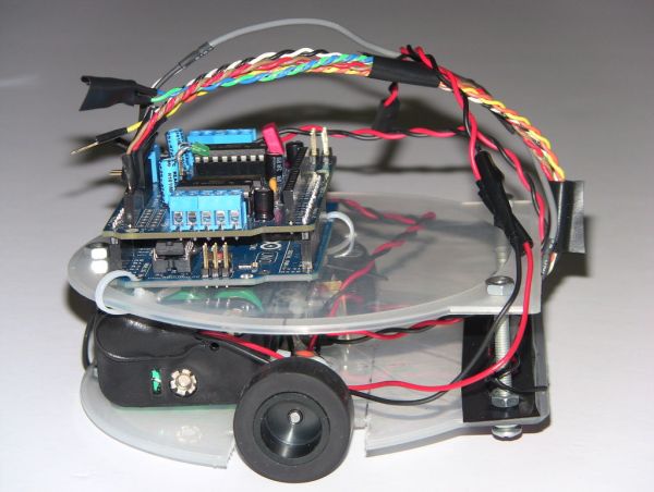
Faz3a II is a DIY Arduino-based line-following robot built on a DVD case platform using an Arduino Uno, Adafruit motor shield, Pololu QTR-8RC sensors (five used), and two Pololu 30:1 micro metal gearmotors. Powered by a 7.2V AA NiMH battery pack, it uses available Arduino libraries for sensors and motor control. The build emphasizes low cost, ease of disassembly, simple mechanical mounting with screws as casters, and careful wiring and labeling to avoid debugging issues.
Parts used in the Faz3a II:
- Arduino Uno
- Adafruit motor shield
- Pololu QTR-8RC line sensor (used 5 sensors)
- Pololu 30:1 micro metal gearmotor x 2
- 7.2V battery pack (6 x AA NiMh)
- DVD case (platform)
- Wires
- Wire straps
- 3 long screws and about a dozen nuts (used as raisers and casters)
- Connectors and soldering supplies (for wiring sensors)
- Drill bits and cutter (for shaping DVD case)
- Arduino IDE 1.0 (software)
- Adafruit motor shield library (software)
- Pololu QTR-8RC Arduino library (software)
UPDATE FEB 2012: This guide is featured on Adafruit’s blog
http://www.adafruit.com/blog/2012/02/14/arduino-based-line-follower-robot/
This is Faz3a II, my first line-following robot, which I also hope to use for maze-solving. I used the Arduino Uno, Adafruit motor shield, Pololu’s QTR-8RC line sensors and motors. You can build a cheaper and lighter version of this robot using the Atmel Atmega328 and the L293D h-bridge. This robot weighs about 300gm and costs about $90 USD.
For my previous robot projects, I used an empty external hard disk enclosure as the robot platform. But for this robot, I am using a DVD case. All in all, I found the round shape of the DVD case a better choice for maneuverability. Not to mention the low cost of DVD cases and ease of stacking layers to hold more parts, with the help of long screws and nuts.
For this project, my task was simplified by the availability of software libraries from Pololu and Adafruit for the sensor and motor shield respectively.
Of course I could have bought a robot kit but I want to be able to take my robot apart anytime to build another one or use the parts in a different project. So if your passion is robotics, consider getting a ready robot kit.
PARTS LIST
ELECTRONICS
Arduino Uno
Adafruit motor shield
Pololu QTR-8RC line sensor. I used only 5 sensors.
Pololu 30:1 micro meta gearmotor X 2
7.2V (6 X AA NiMh batteries)
MISC
DVD case
Wires
Wire straps
3 long screws and about a dozen nuts to act as raisers. The length of the screws depends on the height of the battery brick. One thing to keep in mind when choosing the screws is to get the ones with smooth curved heads and not the flat ones. I use the screw heads as casters.
SOFTWARE
Arduino IDE 1.0
Adafruit motor shield library
Pololu QTR-8RC Arduino library
REFERENCES
I wrote a guide no how to use and test the Pololu QTR-8RC line sensor.
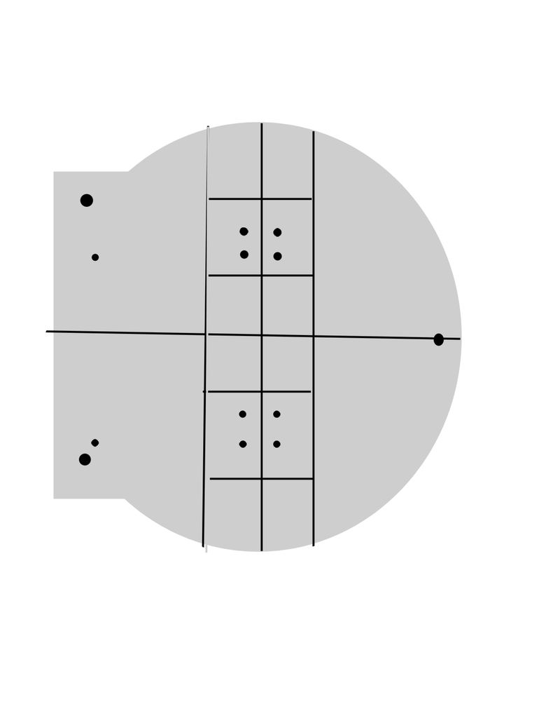
Step 1: Making the robot’s plaform from a DVD case
I used a DVD case for the platform. I marked this DVD case with an erasable pen first. It’s a rough sketch made with a small ruler. I know this design won’t be winning any engineering awards, but it works. Then I used a plain cutter and drill bits to carve out the design on the DVD into the final platform ready for attaching parts. Make sure you drill holes big enough for the wire straps.
Step 2: Assembling the robot’s components
The assembly process is straight forward. I found it very useful to keep notes tracking which motor goes to which motor shield terminal pin and which sensor pin goes into which Arduino pin. Without this, it’s easy to make mistakes that consume long debugging hours.
If you have everything in order, this project should take max 10 hours at a very leisurely pace. The first time I built it, I ran into all sorts of issues because I did not keep track of my wires and because I did not have all the necessary connectors at hand so I did plenty of soldering to connect the sensors to the Arduino. But once I overcame all the wiring hurdles, rebuilding the robot was a matter of 3-4 hour.
The coding and debugging took another few hours the first time around. The second time I rebuilt this robot, it was simply a matter of load and run.
Be mindful of your robot’s left and right motors. Label the motors and the wires as well as the terminals they are connected to and that should spare you needless debugging time. One telltale sign of reversed motors or reversed variable signs is if your robot spins towards the wrong direction constantly.
I powered the robot via the Adafruit motor shield external power pins. I did not need to power the motors separately from the Arduino. The 7.2V power brick did a fine job of powering the whole robot. I had no resets or erratic performance.
As for front and back casters, the soft semi-spherical tip of the screws was good enough to allow smooth movement. No special casters were used. I am sure the screws created extra friction but it did not degrade performance by much. I could have used an LED for caster just as well.
For more Detail: Arduino-based line follower robot using Pololu QTR-8RC line sensor
- What platform was used for the robot?
A DVD case was used as the robot platform. - Which microcontroller and motor controller were used?
An Arduino Uno and an Adafruit motor shield were used. - What line sensors were used and how many?
Pololu QTR-8RC line sensors were used, with five sensors installed. - Which motors powered the robot?
Two Pololu 30:1 micro metal gearmotors powered the robot. - How was the robot powered?
A 7.2V battery pack of 6 AA NiMh cells powered the entire robot via the motor shield external power pins. - Were special casters used for the front and back?
No special casters were used; the smooth curved heads of long screws served as casters. - What software and libraries are required?
Arduino IDE 1.0, the Adafruit motor shield library, and the Pololu QTR-8RC Arduino library were used. - How long does assembly and build typically take?
With everything ready, assembly can take up to 10 hours at a leisurely pace; rebuilding can take 3–4 hours, with extra time for coding and debugging the first time. - How can one avoid wiring and motor direction issues?
Keep notes labeling which motor and sensor wires connect to which motor shield or Arduino pins to avoid mistakes and debugging time.