The Arduino system offers an easy and open-source method for programming microcontrollers. Normally this means using a serial cable or USB cable attached directly to the microcontroller project. But what if your project is floating in a weather balloon, glued to the bottom of a swimming pool or baked into a loaf of bread? It would be great to upload code changes wirelessly, and even greater if you could do it from several kilometers away.
The following example demonstrates how to build a complete wireless solution for uploading code to a remote Arduino microcontroller using a couple of XBee radios, and a handy function for accomplishing wireless resets.
Practical Example
Minimum parts needed: (see Tom Igoe’s parts list for additional details)
- Two 5-15VDC power supplies. Radio Shack sells 4AA Battery Holders that are convenient for remote 3.3 Volt circuits.
- Two XBee OEM RF Modules soldered to breakout boards (as shown here, steps 1 & 2 only )
- One setup to connect an XBee the serial (or USB) port on your computer. My example circuit for XBee firmware uploads works great for this purpose.
- An Arduino set up on a breadboard
- 3.3V regulator
- 2N2222A transistor (or similar)
- LEDs
- Assorted wires
Step 1:
Using a serial connection, program the two XBee radios to talk to each other at 19,200 baud. You can use a program like HyperTerm or ZTerm. On Mac OS X you can use the screen program in a terminal window. (The command would be something like: screen /dev/tty.Keyserial1 9600).
This example uses the default PAN ID of 3332, but you should choose a different one so that other XBee radios in the area do not interfere with your communications. For the first XBee, use the +++ sequence to go into command mode. You should receive an OK message back. Then issue this command: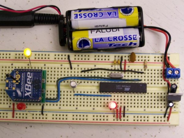
ATID3332,DH0,DL1,MY0,BD4,WR,CN
You have now set the ID to 3332 (remember that this should be changed to something else in your actual command), the destination to 01 (that ‘s the address of your other XBee), the local address to 0 and your baud rate register to 4, which corresponds to 19,200 baud. WR writes the configuration to the firmware, so that the settings are preserved in firmware. From now on you’ll be talking to the XBee at 19,200 baud. [If at some point you want to go back to 9600 baud, the command ATBD3,WR,CN will do the trick.]
Connect your second XBee and again use the +++ sequence to go into command mode. Then issue this command:
ATID3332,DH0,DL0,MY1,BD4,WR,CN
The only difference here is that for the second XBee, you set the destination address to 0 and the local address to 1. The two XBees are now configured to talk to each other.
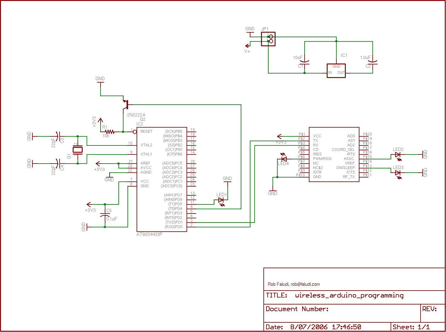
Step 2:Set up the breadboard with a 3.3 Volt regulator for powering the XBee radio. The 3.3V regulator used in this example is arranged (from left to right) Ground-Output-Input, which is different from the 5 Volt one. Make sure that you wire it correctly so that you don’t fry the regulator or anything else on your board. The XBee module is powered with 3.3 Volts and connected to the RX and TX pins 0 and 1 of the Arduino. An LED is connected to pin 13, and the base of a transistor is connected to pin 12. The transistor’s collector is connected to the reset pin and the emitter is connected to ground.
Step 3:
Load the following example code on the Arduino microcontroller, initially using a wired serial or USB connection. The easy way to do this is to put the Arduino microcontroller into one of the regular Arduino boards and upload the code normally.
- An Arduino set up on a breadboard
- 3.3V regulator
- 2N2222A transistor (or similar)
- LEDs
For more detail: Programming Arduino Wirelessly