Summary of Put a Cylon in it!
This article details a DIY project to create a "Cylon Eye" for a Jeep using Total Control Lighting strands, an Arduino-based controller, and a developer shield housed in a purple anodized case. The author explains the software options like CylonEye and HippieCatcher, emphasizing testing the code before drilling holes in the vehicle.
Parts used in the Cylon Eye Project:
- Total Control Awesome Dev Shield Box Kit
- 25 pixel Total Control Lighting strand
- TCL 4-pin male connector
- TCL 4-pin female connector
- 12ft 4-Conductor 22-guage Lead Wire
- 12v to 5v power supply
- USB mini cable
- zip ties
- velcro or mounting screws
Last year the comedy sketch show ‘Portlandia’ made fun of an arts and craft trend, where craft artists would take ordinary items and ‘put a bird on it’. I fell victim to a similar trend in the geek crowd: Take an ordinary silver item and add LEDs to ‘put a cylon in it’. 🙂
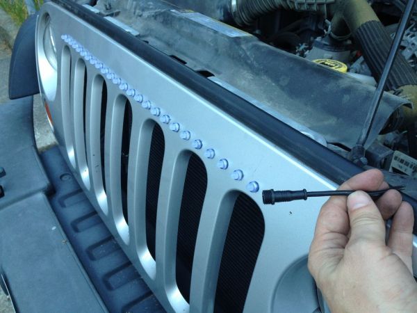 When I saw the Total Control Lighting strands, the first thing that came to mind was sticking these on the front of my Jeep to create a ‘Cylon Eye’. Installing them in the Jeep was a breeze, which then freed me up to tinker with the software. I now have a multi-mode Cylon Eye with a pretty purple control module in my Jeep.
In this Instructable, we’ll be working with Total Control Lightings strands, Arduino programming, and the all new “Total Control Lighting Developers Shield Project Housing” that Cool Neon will be releasing at the upcoming 2013 Maker Fair in San Mateo California. (You saw it here first, folks!)
Parts List:
– Total Control “Awesome Dev Shield Box” Kit ( Seeeduino & TCL Developer’s Shield wrapped in a
lovely Purple Anodized housing)
– 25 pixel Total Control Lighting strand (bullet shaped pixels)
– 1 TCL 4-pin male connector
– 1 TCL 4-pin female connector
– 12ft 4-Conductor 22-guage Lead Wire
– 12v -> 5v power supply (For this Instructable I’m using a cigarette->USB 5v adaptor)
– USB mini cable, for programming and power
– zip ties!
– velcro or mounting screws, depending on your level of permanence desired. 🙂
Tools needed:
– Drill
– 7/16″ drill bit
– 1/16″ drill bit
Also required is an awesome wife who is willing to let me drill holes in our jeep. Thank you Melanie! I love you!
Step 1: Program the controller and test

I know this sounds crazy, but before we get to the fun part of drilling holes in the front of the Jeep, let’s program the controller and test it all out. This will give you a chance to play with the controls and more easily see the resulting changes than when the LEDs are mounted and the controller is in the vehicle.
For the programming/testing stage, you only need four things:
– The TCL Controller
– a 25 pixel strand of TCL lights
– USB mini cable
– a computer with the Arduino IDE installed.*
I have a few code packages available for this project. One is CylonEye, HippieCatcher, and HippieCatcher “Road Safe”.
These are rough drafts, to be kind. I’ll be posting cleaned up code with better comments in a few days.
CylonEye does exactly what you would expect, and a little more. It utilizes the switches and pots on the developer shield to give the user many behavioral modification options without having to rewrite the source.
HippieCatcher functions like a digital ‘cow catcher’. For those too young, a ‘cow catcher’ was a plow-like contraption on the front of locomotive engines that deflect cows off of railroad tracks so as to prevent train derailments. Similarly, the HippieCatcher code cycles through and endless series of morphing colors that start in the center pixel and flow outwards towards the edges. HippieCatcher also makes used of the developer shield inputs to adjust the visual display.
HippieCatcher “Road Safe” is the same as above, but it limits the levels of blue light to keep you street legal.
CylonEye – Cylon_v0_10.ino.zip
HippieCatcher – HippyCatcher_v0_10.ino.zip
HippieCatcher “Road Safe” – HippyCatcher_roadsafe_v0_10.ino.zip
More on the tunable options later.
For now, connect the TCL strand to the four-pin output cable on the TCL controller. Then connect the TCL controller to the computer using your USB cable. I use a dual-head portable hard drive USB cable, which increases the amount of power available to the TCL system. Upload the code of your choice to the controller, and make sure the lights start morphing.
With the controller, TCL strand, and programming verified; we are ready to install the pixels in the vehicle.
*If you are trying to program a Seeeduino (or TCL Developer Controller) on OS X Lion or Mountain Lion, you will need to install FDTI USB drivers. I have a blurb about this on my blog thing. Once you have the drivers, the correct Board is “Arduino Duemilanove / ATMega 328” and the Programmer is “Arduiono as ISP”.
For more detail: Put a Cylon in it!
- What is the main goal of this project?
To install a multi-mode Cylon Eye on the front of a Jeep using LED strands. - How do I test the system before installation?
Connect the TCL strand and controller to a computer with Arduino IDE to upload code and verify lights morph. - Which software codes are available for this project?
CylonEye, HippieCatcher, and HippieCatcher Road Safe are the available rough draft codes. - Does the HippieCatcher code limit blue light?
No, only the HippieCatcher Road Safe version limits blue levels to stay street legal. - What tools are required for drilling holes?
A drill with a 7/16 inch bit and a 1/16 inch bit are needed. - Can I use a standard USB cable for programming?
Yes, but a dual-head portable hard drive USB cable increases power availability. - What driver is needed for OS X Lion or Mountain Lion?
You must install FDTI USB drivers to program a Seeeduino on those operating systems.