Summary of Drive by wire go kart using Arduino
This article details a DIY project converting a go-kart to electronic throttle control using an Arduino. The author replaced a 6hp engine with a 10hp Kohler unit and built a drive-by-wire system to manage the gas pedal, ensuring safety through a kill switch circuit and integrating a servo motor linked to the carburetor via custom brackets and spacers.
Parts used in the Drive by wire go kart:
- Arduino
- Protoshield
- Potentiometer with built-in switch
- LED status light
- Relay
- Manual kill switch
- Servo motor
- "L" bracket
- Erector set parts
- Throttle linkage cable
- Rubber spacers
- Bolts
- Drill
I just got a new go kart engine, i went from 6hp to 10hp. This new kohler engine I got I think was not built to put on a go kart, so I had some trouble finding a way to attach the gas petal. Well after a few days of not really figuring anything out, I remembered that I had gotten an arduino about a week ago, and maybe I could use this to help me out.
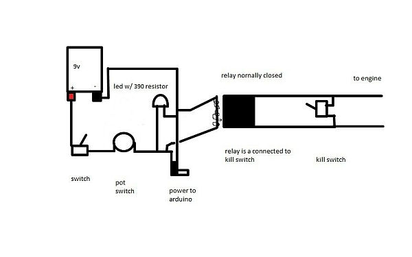
Step 1: Power and safety circuit
below is a diagram of how I go power to the arduino. this way the engine will only start if the arduino is powered on. the first switch is mounted on the box that holds the arduino. the potentiometer i got has a built in switch so to turn on the arduino you have to flip the switch to the box and then turn the potentiometer. i used the led as status light to let me know that the arduino is powered on. i used the relay as a kill switch because if some how the arduino’s battery died and the throttle was opened all the way up, it would be very hard to stop. I also put in a manual kill switch. Also below is what I actually did.
Step 2: Arduino
after i got the arduino i ordered the protoshield and put it together with a few modifications to allow me connect the servo and the pot a little easier. Make sure you know what wire connects to what wire especially if you use a usb port to connect the potentiometer and servo.
Step 3: Servo
Now its time to attach the servo. for this I used an “L” bracket (like the kind you would use for book shelves) and cut it in half. Next I drilled the new holes that were going to be used to mount the servo. following that i built a holder for the servo out of an erector set i had then bolted it to the cut in half “L” bracket. finnally i cut to fit the throttle linkage cable and attached it to the carb and the servo, so when the servo turns it also turns the carb. Also i put rubber spacers to absorb shock.
For more detail: Drive by wire go kart using Arduino
- How does the safety circuit ensure the engine only starts when the Arduino is on?
The power circuit connects the engine start mechanism to the Arduino so the engine cannot run unless the Arduino receives power. - What component serves as the primary kill switch in this project?
A relay is used as a kill switch to stop the engine if the Arduino battery dies or the throttle fails. - Why was a manual kill switch added alongside the relay?
A manual kill switch was added to provide an additional safety layer in case the Arduino's battery died while the throttle was wide open. - How did the author mount the servo motor to the frame?
The author cut an L bracket in half, drilled new holes, and bolted a holder made from an erector set to the bracket. - What material was used to absorb shock between the servo and the linkage?
Rubber spacers were placed to absorb shock within the throttle linkage assembly. - How is the throttle linkage connected to the carburetor?
The throttle linkage cable is cut to fit and attached directly to both the servo and the carburetor. - What modification was made to the protoshield for this build?
Modifications were made to the protoshield to allow easier connections for the potentiometer and servo. - How does the user turn on the Arduino in this setup?
The user must flip a switch on the box and then turn the potentiometer which has a built-in switch.