THE SETUP
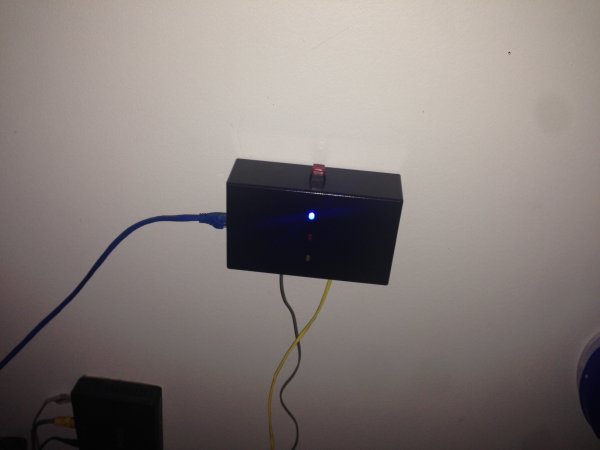
For an interface I thought 3 LEDs would be simple enough: Blue for everything is fine (as blue LEDs are cooler than green ones); red for something is wrong; and yellow for the modem and router are being restarted. I added a button to do the actual restarting as I wanted it to only be done deliberately.
 For the internals I went with:
- Arduino mini pro clone 5v
- ENC28J60 Ethernet connector (datasheet)
- Fotek DC to AC Solid State Relay (SSR) (datasheet)
- LM2936 3.3v linear regulator (datasheet)
- Funduino level shifter (BSS138 mosfet bidirectional shifter, lots of implementations such as this and this, found mine at my local electronics store)
- Resistors, capacitors, etc as per diagram.
For the Ethernet controller, I used the Ethercard library which is on GitHub.
First thing I did was to breadboard the Arduino and the voltage regulator. Reading the data sheet it wanted a capacitor of at least 22uF with a ESR about 0.5 – 5 Ohm (hard to actually tell as the graph is small and has a logarithmic scale). I have a big bag of electrolytic capacitors but could not find a great deal of information on their ESR. There were many tables of typical ESR values (such as http://www.your-book.co.uk/design/esrchart.htm) for electrolytic capacitors but none of them agree and without a datasheet I would have to test it with a specific ESR testing tool. Instead of just hoping that the electrolytic would do I put two in parallel so the resistance would halve and capacitance would double (got the idea from a post in electronic stackexchange). This gave me a nice and stable 3.3v output for the Ethernet controller and level shifter.
Next was getting the Arduino and Ethernet together and check connectivity. I attempted to craft my own level shifter using logic gates but ran into troubles that required more investigation than this little project really called for. So I settled for the level shifter and once connected I progressed to the Ethercard Library. Once it all was connected and the ping example was uploaded the serial connection confirmed that it was working perfectly without any modification.
My next challenge was the Solid State Relay (SSR). When I first added it to the breadboard I had it with a 1k resistor and it wouldn’t work (only 5mA). Reading the datasheet it stated it required 12v at 7.5mA to trigger but at 5v it meant that I needed at least 18mA to trigger (assuming that the trigger is based on power, as if it was resistance the earlier circuit should have worked). Following the datasheet for a normally closed relay I used a 220 Ohm resistor to make sure the SSR has enough current and had the Arduino trigger a transistor to ground the circuit.

I then got a standard power board; stripped the middle of the cord to find the active, neutral and ground; cut and stripped the active; attached it to the SSR; and packed it all up in a standard junction box from the electrical section of the local hardware store.
The pins to the Ethernet in the diagram are as follows (the Arduino pins are defined by the Ethercard library):
- Ground
- CS (from Arduino pin 8)
- SI (from Arduino pin 11)
- SO (from Arduino pin 12)
- SCK (from Arduino pin 13)
- 3.3v (technically 5v to shifter and 3.3v to other side of shifter and to Ethernet)
For more detail: Internet connection indicator box with restart button