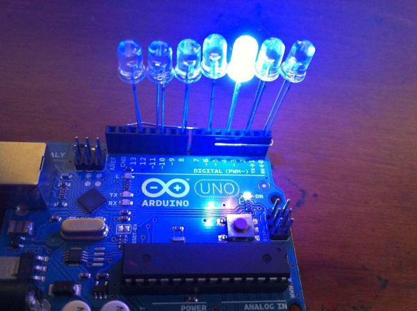
This instructable was designed for beginners in mind, but advanced users can easily adapt it to fit their needs and wants. It only uses a few common components, so you shouldn’t have much trouble putting this together. It’s a good waste of 5 minutes with a satisfying result (at least in my experience), and everything is ready for you to adapt and customize. It’s super cheap and super simple, requires NO breadboarding, and is a good follow-up to blinking and fading an LED. If you’re a beginner who’s tired of just using one LED on the Arduino, look here! If you’re not yet the owner of a breadboard, stay tuned! If you’re still reading this, then stop looking at this infomercial and get on with the project!
Step 1: Gather your materials.
There aren’t a lot of them, but all of them are needed! You’ll need:
-An Arduino
-Some LEDs (I suggest starting with 7, but you can use 14 if you want to!)
-An insulated wire about as long as the Arduino.
At minimum, the wire can be 1 1/2in (or 4cm, for those readers that like the metric system. Go metric!). As proof that it will work, you can insert the wire into the GND pin next to the AREF pin. If the wire can reach Digital I/O pin 0 without much trouble, you’re good to go.
Don’t worry about the LED’s forward voltage, because you’ll only be using them in short bursts that won’t be enough to fry them. My LEDs were each at around 3FV, or 3 forward volts. This is the common amount for most LEDs. If you do decide to use LEDs with a smaller forward voltage, beware. Also, if you adapt the program sampled here and change the delay speed, you might fry your pretty lights! Be careful! If you DO plan to leave an LED on for a prolonged period of time, a 100ohm resistor connected to it should do the trick.
Step 2: Strip the wire.
There really isn’t much to this step. Take your insulated wire and remove the insulation. If you have pliers, use them and your fingernails. Have patience! It has to be a solid-core wire for this to work. Otherwise, you’ll have a lot of tiny strands of metal cluttering your workspace that’s a pain to clean up.
If you have a jumper wire set you bought from Radioshack, with the compartment box and color-coded wire lengths, use the larger red one! It is a perfect size for this project, leaving just enough space to form a “hook” around the female header pins to make it stay in place.
Step 3: Form the wire.
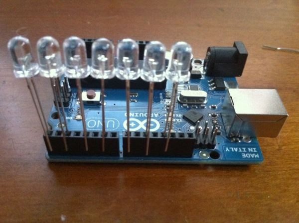
Insert the wire into the GND pin next to the AREF pin so that it’s sticking straight up. Now, bend it so it is pointing down, sticking straight out towards you. Finally, bend it one more time 90 degrees, running parallel with the rest of the digital pins to create your ground rail. If you press the wire against the header pins, the protruding LED cathode wires should touch it. It is essential that all the cathodes of the LEDs touch the stripped wire, or else they won’t make a complete circuit and therefore won’t light up!
Step 4: Insert the LEDs into the corresponding pins.
If you decided to use only 7 LEDs, insert them into each even numbered I/O pin. This means you should have inserted one LED into pins 0, 2, 4, 6, 8, 10, and 12. Remember, the anode (positive lead) is the longer one and is the one that should go into the pin! Leave the cathode (negative lead) hanging outside the pin.
If you plan to use a breadboard, you might want to just jumper the pins directly to the breadboard and insert the LEDs there. However, if you are planning to do so just to make yourself look cool, it’s not worth it! It takes forever to insert each wire into each pin on the Arduino and breadboard. Do so only if you have to! (This means if you plan to use imputs to affect the LEDs, breadboard it. If you’re content with a simple light bar, leave it as it is.)

If you are doing this project for the first time or plan to use imputs, use 7 LEDs. This will (1) leave room for the imput pins you plan to use, and (2) allow spacing for the LEDs to not bunch up and become a big mess.
Also, if you plan to use 14 LEDs, taking advantage of all of the I/O pins on the Arduino, I recommend breadboarding it as well. Heck, rule of thumb: When in doubt, breadboard it!
-Some LEDs
For more detail: Dirt cheap Arduino LED light bar

