Summary of Ultrasonic sensor arduino mega with code
This tutorial shows how to build an Arduino ultrasonic distance indicator using an HC-SR04 sensor, a buzzer, and six LEDs to display distance visually and audibly. It describes wiring to an Arduino (pins given), breadboard assembly, and provides complete Arduino code to read distance and light LEDs and change buzzer tone as objects get closer.
Parts used in the Ultrasonic sensor Arduino mega with code:
- Arduino Uno
- Breadboard
- HC-SR04 Ultrasonic Sensor
- Buzzer
- 2 Green LEDs
- 2 Yellow LEDs
- 2 Red LEDs
- 7 330-ohm Resistors
- Jumper wires
Step 1: Materials Needed
The Materials needed for this project are:(1x) Arduino Uno
(1x) Breadboard
(1x) HC-SRO4 Ultrasonic Sensor
(1x) Buzzer
(2x) Green LEDs
(2x) Yellow LEDs
(2x) Red LEDs
(7x) 330-ohm Resistors
A lot of jumper wires
Step 2: Setup
Connect another jumper wire from a ground pin on the Arduino to the upper channel of the breadboardBuzzer -> pin 3(On Ultrasonic Sensor)
Echo -> pin 6
Trig -> pin 7(In Order from Right to Left)
LED1 -> pin 8
LED2 -> pin 9
LED3 -> pin 10
LED4 -> pin 11
LED5 -> pin 12
LED6 -> pin 13The jumper wires connected to the LEDs should be connected to the lead on the right, while the left lead of the LED should be connected to the ground channel via a 330-ohm resistor.
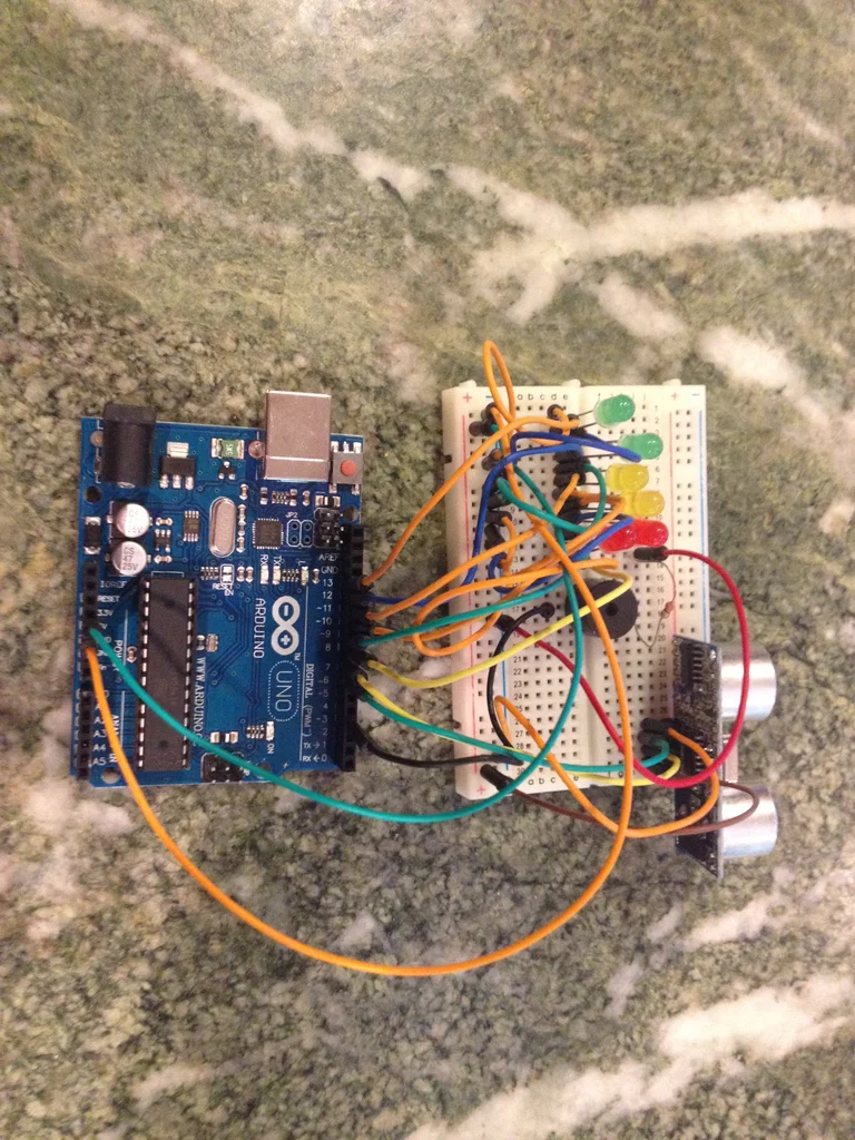
Step 3: Assembly: Breadboard
Step 4: Assembly: Ultrasonic Sensor
Now it’s time to attach the HC-SRO4 ultrasonic sensor. It is easiest to place the ultrasonic sensor as far right to the breadboard as possible. Referring back to the setup picture, you should connect the ground pin on the ultrasonic sensor to the ground channel on the breadboard. Next, connect the Echo pin on the sensor to pin 6 on the Arduino. Now connect the Trig pin on the sensor to pin 7 on the Arduino, and lastly connect the VCC pin on the sensor to the 5-volt channel on the breadboard. If you did that all correctly, your assembly should look like the picture above.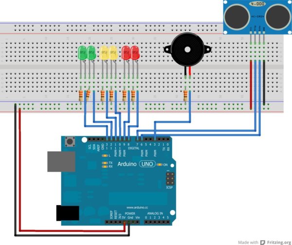
Step 5: Assembly: LEDs
Next is connecting the LEDs to the breadboard and Arduino. Once again referring back to the setup picture, attaching the LEDs is pretty basic, just with a lot of repetition. The way to connect them is to connect the anode, or the longer leg, or the one on the right, to a pin on the Arduino with a jumper wire, and to connect the cathode, or the shorter leg, or the one on the left, to the ground channel on the breadboard using a 330-ohm resistor. Then just repeat that step for all six of the LEDs, with the red LED all the way on the right being connected to pin 8 on the Arduino, the anode of the red LED to the left of that one being connected to pin 9 on the Arduino, and so on. The last LED, that being the green LED all the way on the left, should have its anode, or right leg, connected to pin 13 on the Arduino. Once you have done that, your setup should look something like this.
Step 6: Assembly: Buzzer
Step 7: The Code

Now that you have finished the physical setup of the build, now its time for the code. I assume that you already have the Arduino program on your computer, so now all you have to do is copy and paste the code from below.
#define trigPin 7
#define echoPin 6
#define led 13
#define led2 12
#define led3 11
#define led4 10
#define led5 9
#define led6 8
#define buzzer 3

int sound = 250;

void setup() {
Serial.begin (9600);
pinMode(trigPin, OUTPUT);
pinMode(echoPin, INPUT);
pinMode(led, OUTPUT);
pinMode(led2, OUTPUT);
pinMode(led3, OUTPUT);
pinMode(led4, OUTPUT);
pinMode(led5, OUTPUT);
pinMode(led6, OUTPUT);
pinMode(buzzer, OUTPUT);

}

void loop() {
long duration, distance;
digitalWrite(trigPin, LOW);
delayMicroseconds(2);
digitalWrite(trigPin, HIGH);
delayMicroseconds(10);
digitalWrite(trigPin, LOW);
duration = pulseIn(echoPin, HIGH);
distance = (duration/2) / 29.1;

if (distance <= 30) {
digitalWrite(led, HIGH);
sound = 250;
}
else {
digitalWrite(led,LOW);
}
if (distance < 25) {
digitalWrite(led2, HIGH);
sound = 260;
}
else {
digitalWrite(led2, LOW);
}
if (distance < 20) {
digitalWrite(led3, HIGH);
sound = 270;
}
else {
digitalWrite(led3, LOW);
}
if (distance < 15) {
digitalWrite(led4, HIGH);
sound = 280;
}
else {
digitalWrite(led4,LOW);
}
if (distance < 10) {
digitalWrite(led5, HIGH);
sound = 290;
}
else {
digitalWrite(led5,LOW);
}
if (distance < 5) {
digitalWrite(led6, HIGH);
sound = 300;
}
else {
digitalWrite(led6,LOW);
}

if (distance > 30 || distance <= 0){
Serial.println("Out of range");
noTone(buzzer);
}
else {
Serial.print(distance);
Serial.println(" cm");
tone(buzzer, sound);

}
delay(500);
}
Once you’ve done that, and you’ve plugged in your Arduino to your computer, run the code and you’re finished. If you’ve followed all the directions, the closer you’re hand gets to the HC-SRO4, the LEDs should progressively light up until, and the closer your hand gets, the buzzer will produce a higher tone each time.
Source: Ultrasonic sensor Arduino mega with code
- What Arduino pin is the ultrasonic sensor trig connected to?
The trig pin is connected to Arduino pin 7. - What Arduino pin is the ultrasonic sensor echo connected to?
The echo pin is connected to Arduino pin 6. - How are the LEDs connected to the Arduino and breadboard?
Each LED anode (longer/right leg) is connected to its Arduino pin with a jumper and each cathode (shorter/left leg) is connected to the breadboard ground channel through a 330-ohm resistor. - Which pin is the buzzer attached to?
The buzzer longer leg is attached to Arduino pin 3 and its shorter leg to the ground channel; a resistor on the ground leg is recommended to reduce volume. - What happens when an object is out of the sensor range?
The code prints Out of range to Serial and noTone is called so the buzzer stops. - How does the project indicate decreasing distance?
As distance decreases LEDs light progressively (pins 13 to 8) and the buzzer tone frequency increases via the sound variable. - What serial baud rate does the code use?
The code uses Serial.begin(9600), so 9600 baud. - Which Arduino pins drive the six LEDs?
The LEDs are driven by pins 13, 12, 11, 10, 9, and 8 respectively. - What distance thresholds trigger the LEDs in the code?
LEDs are triggered at distances less than or equal to 30 cm, and then at less than 25, 20, 15, 10, and 5 cm for successive LEDs. - How often does the code update readings?
The loop ends with delay(500), so readings update every 500 milliseconds.