
Summary of Safe and simple AC PWM Dimmer for arduino / Raspberry pi
This project describes an AC mains dimmer using a MOSFET (BUZ41A) inside a diode bridge, driven by a gate supply harvested from the MOSFET voltage, with an optocoupler for isolation and PWM control from Arduino or Raspberry Pi. It includes circuit explanation, assembly steps, Arduino fading sketch, and Raspberry Pi wiringPi GPIO PWM setup and scripting instructions.
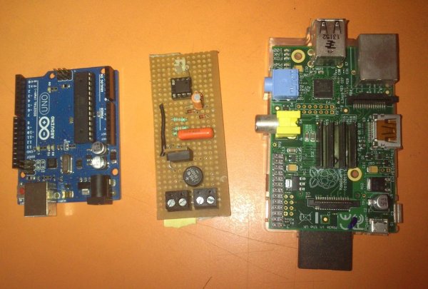
Parts used in the Dimmer With MOSFET:
- BUZ41A MOSFET (500 V / 4.5 A)
- Diode bridge
- D6 (rectifier diode)
- C2 (filter/holding capacitor)
- R5 (current-limiting resistor for rectifier)
- R3 and R4 (voltage divider resistors for power regulation)
- C1 (filter capacitor for regulator)
- D1 (zener or clamp diode to limit to 10 V)
- Optocoupler CNY65
- R2 (gate drive resistor, 22 kΩ)
- R1 (LED protection/current-limiting resistor for optocoupler)
- T1 (transistor within optocoupler used for switching)
- Incandescent lamp (load used in measurements)
- Additional passive components as required for assembly (wires, PCB, connectors)
- Raspberry Pi (for PWM control)
- Arduino (optional, for PWM control example)
Dimmer With MOSFET
This circuit shows that dimmers intended for use at mains voltage do not always have to contain a triac.
Here, a MOSFET (BUZ41A, 500 V/4.5A) in a diode bridge is used to control the voltage across an incandescent bulb with pulse-width modulation (PWM). The power supply voltage for driving the gate is supplied by the voltage across the MOSFET.
add on board: raspberry pi diy add-on board
Step 1: Circuit diagram and description
The power supply voltage for driving the gate is supplied by the voltage across the MOSFET. D6, R5 and C2 form a rectifier. R5 limits the current pulses through D6 to about 1.5 A (as a consequence it is no longer a pure peak rectifier). The voltage across C2 is regulated to a maximum value of 10 V by R3, R4, C1 and D1. An optocoupler and resistor (R2) are used for driving the gate.
R1 is intended as protection for the LED in the optocoupler. R1 also functions as a normal current limiting device so that a ‘hard’ voltage can be applied safely. The optocoupler is anold acquaintance, the CNY65, which provides class-II isolation. This ensures the safety of the regulator. The transistor in the optocoupler is connected to the positive power supply so that T1 can be brought into conduction as quickly as possible. In order to reduce switching spikes as a consequence of parasitic inductance, the value of R2 has been selected to be not too low: 22 kΩ is a compromise between inductive voltages and switching loss when going into and out of conduction.
An additional effect is that T1 will conduct a little longer than what may be expected from the PWM signal only. When the voltage across T1 reduces, the voltage across D1 remains equal to 10 V up to a duty cycle of 88 %. A higher duty cycle results in a lower voltage. At 94 % the voltage of 4.8 V proved to be just enough to cause T1 to conduct sufficiently. This value may be considered the maximum duty cycle. At this value the transistor is just about 100 % in conduction. At 230 V mains voltage, the voltage across the lamp is only 2.5 V lower, measured with a 100-W lamp. Just to be clear, note that this circuit cannot be used to control inductive loads. T1 is switched asynchronously with the mains frequency and this can cause DC current to flow.
Electronic lamps, such as the PL types, cannot be dimmed with this circuit either. These lamps use a rectifier and internally they actually operate off DC.A few remarks about the size of R3 and R4. This is a compromise between the lowest possible current consumption (when the lamp is off) and the highest possible duty cycle that is allowed. When the duty cycle is zero, the voltage across the resistors is at maximum, around 128 V with a mains voltage of 230 V. Because (depending on the actual resistor) the voltage rating of the resistor may be less than 300 V, two resistors are connected in series. The power that each resistor dissipates amounts to a maximum of 0.5 W. With an eye on the life expectancy, it would be wise to use two 1-W rated resistors here.
Author: Ton Giesberts – Copyright: Elektor Electronics
Circuit description source: http://www.learningelectronics.net/circuits/dimmer-with-mosfet.html
Step 2: Assembling Steps
Step 3: AC PWM dimmer with arduino
Step 4: Arduino script
Fading
This example shows how to fade an LED using the analogWrite() function.
The circuit:
* LED attached from digital pin 9 to ground.
Created 1 Nov 2008
By David A. Mellis
modified 30 Aug 2011
By Tom Igoe
http://arduino.cc/en/Tutorial/Fading
This example code is in the public domain.
*/
int ledPin = 3; // LED connected to digital pin 9
void setup() {
// nothing happens in setup
}
void loop()
{
// fade in from min to max in increments of 5 points:
for(int fadeValue = 0 ; fadeValue <= 255; fadeValue +=1) {
// sets the value (range from 0 to 255):
analogWrite(ledPin, fadeValue);
// wait for 30 milliseconds to see the dimming effect
delay(50);
}
// fade out from max to min in increments of 5 points:
for(int fadeValue = 255 ; fadeValue >= 0; fadeValue -=1)
{
// sets the value (range from 0 to 255):
analogWrite(ledPin, fadeValue);
// wait for 30 milliseconds to see the dimming effect
delay(50);
}
// analogWrite(ledPin, 25);
}
Step 5: AC PWM Dimmer with Raspberry Pi
Step 6: Raspberry pi gpio setup
step 1 install wiringPi GPIO library
http://wiringpi.com/download-and-install/
step 2: GPIO setup
open lxterminal/ root terminal program
type
sudo su # for super user privilege
gpio readall #display the gpio status
gpio mode 1 PWM # set the gpio -18 [wiringPi gpio-1] mode to PWM
gpio readall # check the new status of wiringpi pin1/gpio -18 mode
gpio mode 1 0 #off
gpio mode 1 1 #pwm level 1
gpio mode 1 5 #pwm level 5
step 3: how to create and run a script file in raspberry pi
step1: open lxterminal/rootterminal
step 2: sudo su # for super user privilege
step 3:sudo nano PWM_test.sh #open an editor with file name PWM_test.sh
step 4: type the program,save and exit from editor [ ctrl+X and y for save and exit ]
step 5: bash PWM_test.sh #run the script
step 6: ctrl+z / ctrl+c #exit from the program
For more detail: Safe and simple AC PWM Dimmer for arduino / Raspberry pi
- How is the gate drive power supplied?
The gate drive power is supplied by rectifying the voltage across the MOSFET using D6, R5 and C2 and regulated to about 10 V by R3, R4, C1 and D1. - Can this circuit dim electronic fluorescent or PL lamps?
No, electronic lamps such as PL types cannot be dimmed with this circuit because they use a rectifier and operate off DC internally. - Does the dimmer use a triac?
No, the dimmer uses a MOSFET in a diode bridge instead of a triac. - What provides isolation between mains and control?
An optocoupler CNY65 provides class-II isolation between the mains-side regulator and the control circuitry. - Can this dimmer be used with inductive loads?
No, the circuit cannot be used to control inductive loads because asynchronous switching with the mains can cause DC currents to flow. - What limits current pulses through D6?
R5 limits the current pulses through D6 to about 1.5 A, so the rectifier is not a pure peak rectifier. - What is the role of R2 in the gate drive?
R2 (22 kΩ) limits switching spikes from parasitic inductance and balances between inductive voltages and switching losses. - What is the maximum practical PWM duty cycle?
The practical maximum duty cycle is about 94%, where the gate drive voltage falls to about 4.8 V and the transistor is nearly fully on. - How are R3 and R4 chosen?
R3 and R4 values are a compromise between low current consumption when the lamp is off and allowing the highest possible duty cycle, and are implemented as two series resistors for voltage rating and power dissipation. - How can Raspberry Pi generate PWM for this dimmer?
Install wiringPi, set the appropriate wiringPi pin to PWM mode (gpio mode 1 PWM), and run scripts to change PWM levels as shown in the GPIO setup steps.