Summary of Soundgraffiti with arduino mega
This installation, Soundgraffiti, uses sprayed water to bridge a tiny gap in copper plate sensors, closing a circuit that signals an Arduino and laptop running Pure Data to light LEDs and trigger sample loops. The team designed wiring schematics, laser/CNC-cut boards and sensors, and wrote Arduino and Pure Data code to manage 15 LEDs and many inputs.
Parts used in the Soundgraffiti:
- LEDs
- Breadboard
- Arduino (Uno or Mega)
- Laptop
- Pure Data software
- Many cables
- Soldering iron
- Solder (tin)
- Audio samples / music
- Plexiglass (plexi)
- Large piece of MDF or other wood
- Lasercutter
- CNC machine
- Copper plates
So we haven been working on the new soundgraffiti board.
This is an installation wich creates sounds using sprayed water.
The connection is made with water. We used copper plates as our sensor. the plates had a cutout line in the middle of 0,1 mm. Once water hit this line it would connect both sides of the plate an close the circuit.
The closed circuit sends a ‘on’ status to the arduino and our laptop with pure data. This started the burning of a white LED and the begin of a sample loop.
What you need:
-Led’s
-breadboard
-arduino (uno/mega)
-laptop
-Pure data software
-a lot of cables
-soldering iron
-tin
-samples/music
-plexi
-a big piece of mdf/or other wood
-lasercutter
-Cnc
-copper plates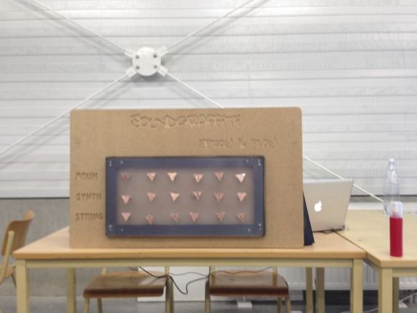
Step 1:
the first thing we needed to do was to check how we could build this installation, using water as a connector.
We cut out a small piece from a copper plate so the circuit would be broken.
We tried out this connection with just one sensor and one LED light.
When this worked we started to create our wiring for 2-3,.. led’s.
Step 2:
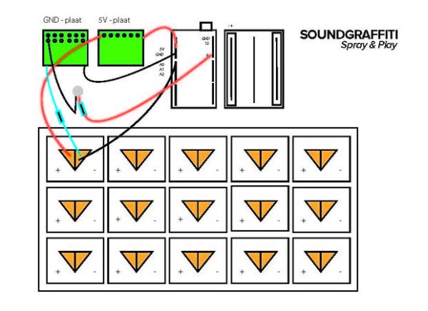
It was very important that we had a clear visual schedule that explained our wiring.
At the end of our project we used more than 80 wires so a clear schedule comes in handy.
We made ours in illustrator, for each sensor/Led it is the same.
This was completed so we started creating our code for all the 15LED’s.
The code for Arduino and pure date you can find at the last step.
Step 3:
When all of that was done we began to create our copper plate sensors and the drawing for our board.
The board has been drawn in illustrator and cut out using a cnc.
The copper plates are cut out using a cutter.
For more detail: Soundgraffiti with arduino mega
- How does the installation detect sprayed water?
Water bridges a 0.1 mm cutout in copper plates, closing the circuit and sending an on status to the Arduino and laptop. - Can one sensor trigger an LED and a sample?
Yes, a single sensor closing the circuit lights a white LED and starts a sample loop via Pure Data. - What microcontroller is used?
The project uses an Arduino Uno or Mega. - How are the copper plate sensors made?
Copper plates are cut with a cutter and a 0.1 mm gap is created so water can bridge the sides. - What software handles the sound triggering?
Pure Data on a laptop manages the sample loops and responds to the Arduino signals. - How many LEDs and wires were used?
The project included 15 LEDs and at times more than 80 wires. - How was the board produced?
The board drawing was made in Illustrator and cut out using a CNC. - Why is a visual wiring schedule important?
Because the installation used many wires (over 80), a clear wiring schedule aided organization and consistent wiring across sensors and LEDs.