A while ago, as my first microcontroller project, I made a Pong game on a 5×7 LED display, but then nothing became of it. Recently I was given a hard hat as part of a uniform (for an engineering competition) and told to customize it, and remembered pong.
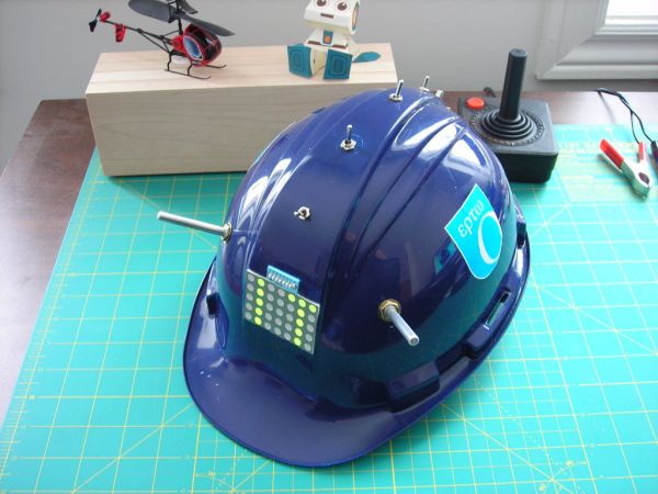
In this instructable I will show you how to make a scrolling LED display and how to install it in a hard hat. It also plays pong!
![]() LED_Diaplay_Code.zip91 KB
LED_Diaplay_Code.zip91 KB
Step 1: Materials
Parts:
-2 10k potentiometers
– 3 4.7 kOhm resistors
-4 SPST toggle switches
-1 5×7 bicolour LED display
-1 8 pin dipswitch
-1 Hardhat
-1 atmega168 microcontroller (or arduino)
-1 28 Pin ‘skinny’ socket
-1 breadboard
-1 3.7V lithium polymer battery
-Wire
-Solder
-Hot Glue
Tools:
-Soldering Iron
-Hot Glue Gun
-Wire Stripper
-Hobby Knife
-Plexiglas Cutting Knife
– Microcontroller Programmer (optional)
Step 2: Solder the Display
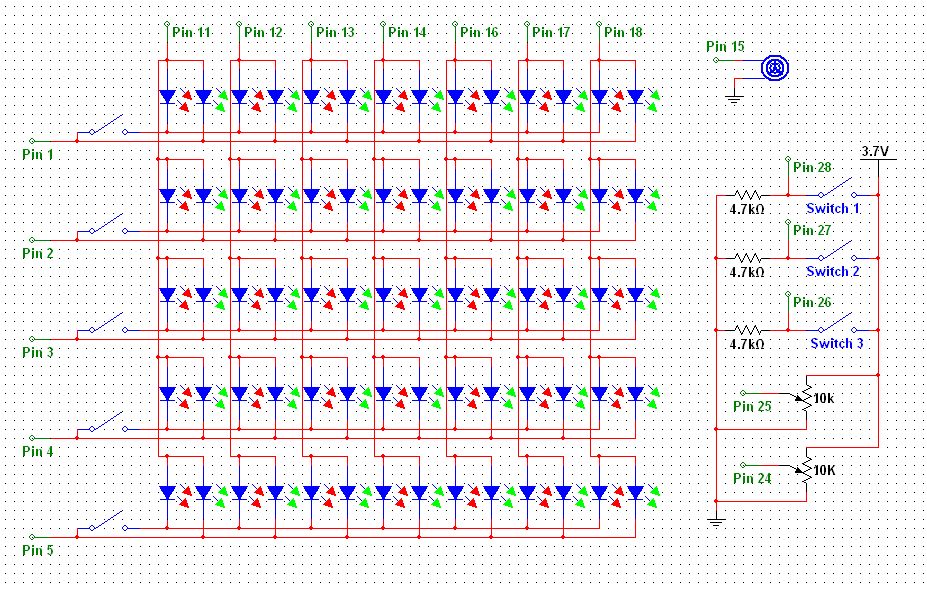
For the first step, you need to solder wires to the display. You will also need to solder one switch from the dip switch between the two colours’ cathodes for each row. To make it clearer I have attached a schematic of the display in the pictures (click the [i] on the picture to get the full sized version).
For the next step I used switch 8 for a ‘travel mode’. This is so the hat isn’t accidentally turned on in a bag and drained.
Step 3: Solder the Power Connections
For this step you need to solder the microcontroller socket to the breadboard. Then solder all of the power connections to the microcontroller socket pins. If you are unsure which pins to solder, there is a good reference here.
Step 4: Attach the LEDs to the Board
Now you need to attach the wires coming off the LED display to the breadboard. To help with this see the attached schematic, or you can look in the code in the intro to find the output pins on the arduino.
Step 5: Solder Switches
Next solder the switches to the breadboard. I have again attached the schematic in the pictures of this step.
For each switch, it is one contact of the switch connected to the corresponding microcontroller pin and the other to the positive voltage. There is also one resistor from the input pin to ground for each switch.
For more detail: LED Hat Display with Pong using an Arduino