Summary of Arduino Electronic Dice using random numbers
This article guides beginners in building an electronic dice using an Arduino, seven LEDs, resistors, jumper wires, and a motion sensor. The project uses simple code with comments to explain the random number generation logic. It is designed for easy learning and assembly on either a breadboard or protoshield.
Parts used in the Electronic Dice:
- Arduino or a clone
- 11 Jumper Wires (or stripped wires)
- 7 Resistors (330ohms)
- 7 LEDs (green)
- 1 tactile switch or motion sensor
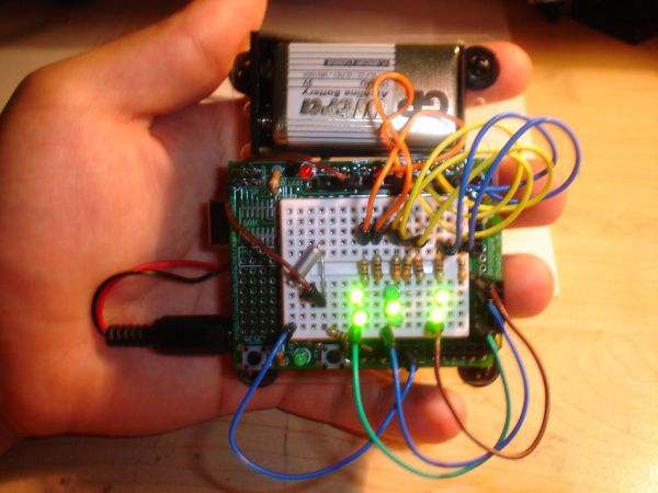
This instructable will show you how to make an electronic dice with minimal experience using 7 LEDs, resistors, jumper wires, and of course the arduino (or arduino clone). I wrote this instructable for anyone to easily follow along and learn more about the arduino. Questions are welcome and will be answered as soon as possible. For less experienced users the code for the arduino is in “longhand” and several comments are included for better understanding of the code being uploaded into the arduino.
Step 1: Parts list
Arduino or a clone ( I’m using a protoshield but a breadboard will work the same way)
11 Jumper Wires (or stripped wires in order to make connections on a breadboard)
7 Resistors (I used 330ohms) (ORANGE)(ORANGE)(BROWN)(GOLD)
7 LEDs ( I used green)
1 tactile switch or motions sensor (I used a motion sensor)
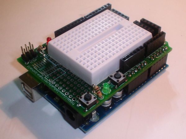
Step 2: Jumper Setup
In this step you will need to plug in 7 of the 11 wires. Jumper will be placed in digital plugs 2, 4, 5, 6, 7, 8, and 10; the other sides will be placed in the breadboard as shown below.
11 Jumper Wires
7 Resistors
For more detail: Arduino Electronic Dice using random numbers
- What components are needed to build this electronic dice?
You need an Arduino or clone, 11 jumper wires, 7 resistors, 7 LEDs, and one tactile switch or motion sensor. - Can I use a breadboard instead of a protoshield?
Yes, a breadboard will work the same way as the protoshield mentioned in the guide. - How many jumper wires are required for the setup?
The project requires 11 jumper wires, though only 7 are plugged into digital plugs during the specific setup step. - What resistor value is recommended for the LEDs?
The article suggests using 330ohm resistors, identified by the color bands orange, orange, brown, and gold. - Does the code require advanced programming skills?
No, the code is written in longhand with several comments included for better understanding by less experienced users. - Which digital pins are used for the LED connections?
The jumper wires are placed in digital plugs 2, 4, 5, 6, 7, 8, and 10. - What type of input device can trigger the dice roll?
You can use either a tactile switch or a motion sensor as the input device. - What color LEDs were used in this example project?
The author used green LEDs for the demonstration.