Summary of Wise Clock 3 – Arduino-based geeky alarm clock
Wise Clock 3 is an open-source, hackable clock based on the ATmega644P microcontroller that displays time, temperature, date, and user-editable messages from an SD card. It features multi-color LED display modes including "Pong" and "Pacman," functions as an alarm, scoreboard, or countdown timer, and is programmable via Arduino IDE. The clock uses a highly accurate DS3231 real-time clock chip with battery backup and comes as a kit including a PCB, LED display, and hardware parts. The design supports future expansions and is enclosed in plexiglass plates.
Parts used in the Wise Clock 3:
- PCB
- ATmega644P microcontroller with Arduino bootloader
- DS3231 real-time clock chip (pre-soldered)
- SD card socket (pre-soldered)
- 40-pin socket for the controller
- 16 MHz crystal
- Two 22pF capacitors
- CR1220 backup battery for RTC
- Battery holder for coin battery
- miniB USB connector
- 3.3V voltage regulator (L78L33ACZ)
- Piezoelectric buzzer
- Nine 10K resistors
- Three 4.7K resistors
- One 100 ohm resistor (optional)
- Blue LED (optional, power indicator)
- Four right-angle micro push buttons
- 6-pin right-angle male header (FTDI connector)
- Two 16-pin female headers (display connectors)
- Three 100nF decoupling capacitors
- 3216 bi-color LED display (from Sure Electronics)
- Laser-cut transparent or smoky plexiglass plates
- Hardware parts: standoffs, nuts, screws, washers
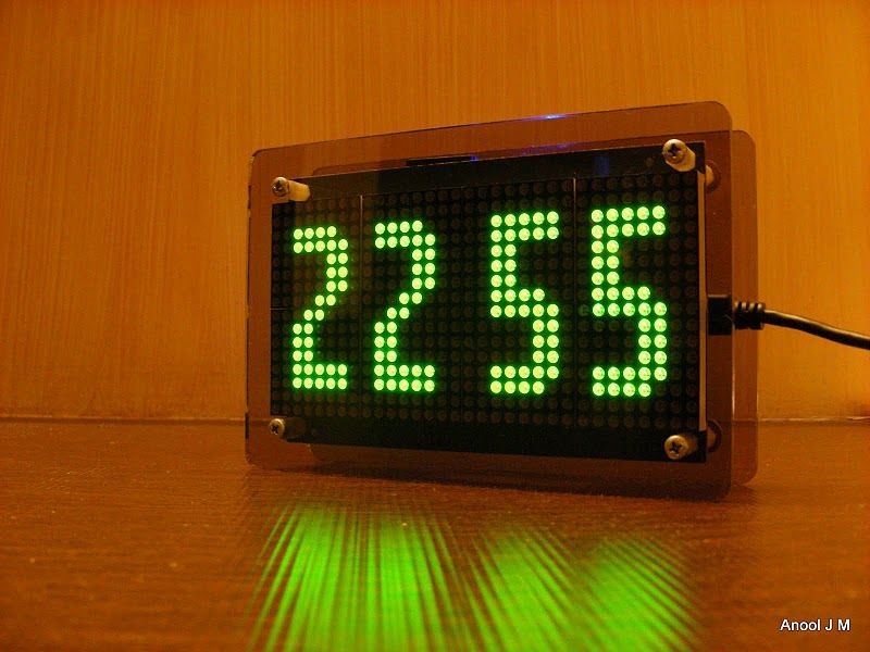
In addition, Wise Clock 3 can show the time in “Pong” mode or “Pacman” mode. It can also display the date, including the day of the week and the temperature.
Another catchy function is to show a personalized message (e.g. “Happy birthday”). Wise Clock 3 can be also used as an alarm clock, as a scoreboard or as a countdown timer. To see the other features, please check out the “User manual”, the last step of this instructable.
Updated Sep 5, 2011
Convert Wise Clock 3 to Night and day clock as described here.
The clock is shown in action here:
Some technical details:
– based on ATmega644P microcontroller;
– open source, published, software and hardware;
– user-programmable through a 6-pin FTDI cable (or breakout);
– uses extremely accurate (+/- 2 minutes per year), temperature-compensated, real time clock chip DS3231;
– multi-color (red, green, orange) display with 32×16 LEDs;
– compatible and programmable with the Arduino IDE.
Wise Clock 3 can be purchased as a complete kit, here .
Step 1: The Wise Clock 3 kit – parts list
– a set of electronic components (see list below) and the PCB;
– the 3216 bi-color LED display from Sure Electronics;
– a pair of laser-cut transparent or smoky plexiglass plates;
– a set of hardware parts (standoffs, nuts, screws, washers).
Photo 2 shows the electronic components of the kit. They are:
– PCB;
– ATmega644P controller with Arduino bootloader (also programmed with the latest version of the software);
– DS3231 real-time-clock (pre-soldered to the board);
– SD card socket (pre-soldered to the board);
– 40-pin socket for the controller;
– 16MHz crystal and 2 capacitors 22pF;
– CR1220 backup battery for RTC;
– holder for the coin battery;
– miniB USB connector;
– 3V3 voltage regulator;
– piezoelectric buzzer;
– 9 resistors 10K;
– 3 resistors 4K7;
– resistor 100 ohms (optional);
– blue LED (optional) – power indicator;
– 4 right-angle micro push buttons;
– 6-pin right-angle male header (FTDI connector);
– 2 x 16-pin female headers (display connectors);
– 3 decoupling capacitors 100nF.
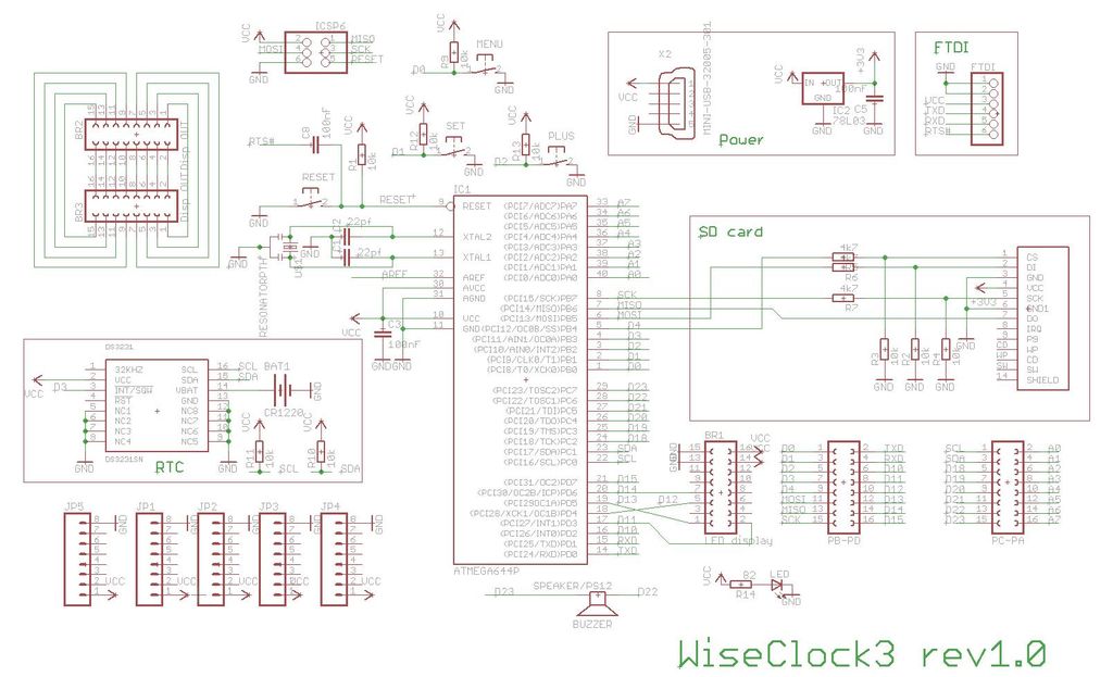
Step 2: Hardware – schematic and board
The Eagle files can be downloaded from here: schematic , board .
The Wise Clock 3 board was designed to plug directly into the 3216 bi-color 3mm LED display from Sure Electronics . Therefore, there is no need for cables/wires when connecting the board to the display.
Note: The Wise Clock 3 board can connect and drive more than one display, as shown and explained here .
The PCB has a small prototyping area that can be used to add components for future expansions, like photo resistor for automatic light dimming of the display, infrared receiver to control the clock remotely, tilt switch etc. Of course, all these new sensors will have to be supported in the software as well.
The clock function is performed by the on-board RTC (real-time-clock) chip DS3231. This is far superior to (and more expensive than) DS1307, since it has a deviation of only +/-2 minutes per year, at most. The accurate time is kept even when the clock is not powered, due to the on-board backup battery.
Step 3: Soldering Wise Clock 3 components
To assemble the board, follow this process:
1. Place and solder the miniB USB connector; actually, since this connector is only used for power, only the two extreme pins (1 and 4) must be soldered; the middle two can be left untouched. Make sure the connector is solidly anchored to the board through the 4 lateral holding pads; there will be lots of mechanical tension when the power cable is plugged/unplugged.
2. Solder the 100 ohm resistor (brown black brown), indicated on the PCB as R14, then the LED, paying attention to its orientation. The shorter pin, the cathode, goes into the left (as you look at the PCB as in photo 2 below) hole. At this point, by plugging in the power cable, the LED should light up (photo 3).
3. Solder resistors R5, R6, and R7, all 4K7 (yellow purple black brown brown), as shown in photo 4.
4. Solder the rest of the resistors, all 10K, as shown in photo 5 below.
Note that there are 9 resistors of 10K value (brown black orange): R1, R2, R3, R4, R9, R10, R11, R12, R13.
5. Solder the 40-pin socket, then the battery holder and the 4 buttons, as shown in photo 6.
6. Solder the 3 decoupling capacitors (100nF, labeled “104”): C3, C5, C8. Then continue with soldering the two smaller ones C1, C2 (both 22pF), as shown in photo 7.
7. Insert the crystal (the small, metallic, oval cylinder, with 2 pins, labelled “16.000” on its top) in its position on the left side of the microcontroller socket, indicated by an oval (see the above image). Orientation is not important for the crystal.
Then insert the 3V3 voltage regulator (black, 3-pinned, semi-cylindric part labeled “L78L33ACZ”) as indicated on the silkscreen by the half-cylinder on the right side of the microcontroller socket (its orientation is very important), then solder in place.
Next solder the 6-pin male header, and then the piezoelectric buzzer (its orientation is not important).
Look at the last picture (photo 9) of the final assembled board before soldering, to make sure you have these parts placed correctly.
8. (Photo 8) Insert the two 16-pin female headers on the back of the board (opposite to the parts side) and solder them on the top (parts) side.
To get the best alignment possible on these headers, insert the 16-pin headers into their sockets (in the display), then solder the board on top. (This is similar to the way the male headers are soldered on an Arduino-shield.)
9. It is time to add now the preprogrammed ATmega644P microcontroller. Before inserting it in the socket, slightly bend both sets of its pins on a table, so that they become parallel. Position the chip carefully on top of the socket, paying attention to its orientation: pin 1, marked with an arrow (triangle), must be close to the upper side of the board. Push the chip firmly into the socket.
Next insert the coin battery in the battery holder.
The assembled board should look like in the last picture (photo 9) below
Step 4: Mechanical assembly – attach display and enclosure
The Wise Clock 3 PCB was designed to be plugged directly into the 3216 3mm LED display from Sure Electronics. But it can be also used with the 5mm version of the display, by using the provided 16-wire ribbon cable.
To plug the board into the display, gently push the board into the connectors, after you properly aligned them (photo 3).
Next step is to attach the simple enclosure, which is made of a pair of plexiglass plates, either 3mm smoky or 4mm clear, with the dimensions shown in photo 4. The DXF file, used for laser-cutting, is available for download here .
The 2 plates are directly attached to the display, with the standoffs in the four corners. (The board fits snugly between the display and the back plate and does not need any other attachment or screw.) The longer standoffs go in the back of the display, and are screwed into the shorter standoffs placed in the front of the display. Note that the 4 washers provided are to be placed on the back of the display, between the standoffs and the display’s board, essentially extending the longer standoffs.
For more detail: Wise Clock 3 – Arduino-based geeky alarm clock