Summary of LED Microcontroller Debug Module
The article describes a Microcontroller Debug Module (MDM) that transplants an MCU off a breadboard to a small module connected by a 40-pin ribbon to a substitution PCB. Each MCU port is buffered by 74LS541 line drivers that drive red/green LEDs per pin without loading the MCU. Features include DIP switches to disable ports, onboard oscillator, ICSP header, and support for PIC18 28/40-pin devices. Revision 0.3 includes corrections and added features. The design aims to simplify visual debugging without modifying the target circuit.
Parts used in the Microcontroller Debug Module (MDM):
- MDM PCB - 1 Piece
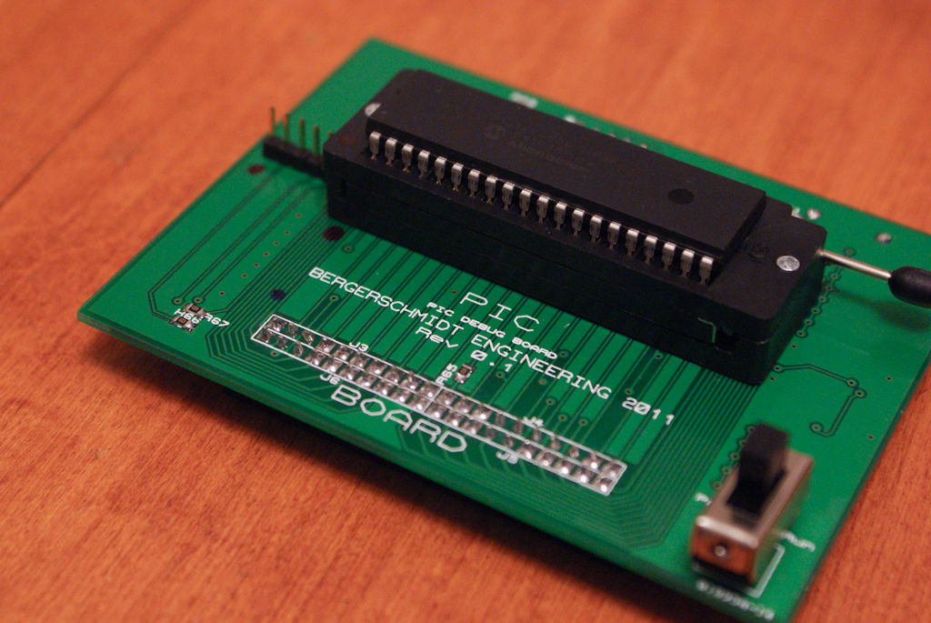
- MCU Substitution PCB - 1 Piece
- 74LS541 Tri-state buffer/line driver - 4 Pieces
- 0805 SMT LED GREEN 2V 20mA - 32 Pieces
- 0805 SMT LED RED 2.1V 20mA - 32 Pieces
- 0805 330 ohm SMT resistor - 64 Pieces
- 0805 10k ohm SMT resistor - 6 Pieces
- 0805 10nF SMT capacitor - 5 Pieces
- 0805 100nF SMT capacitor - 1 Piece
- 4 position SPST DIP switch - 1 Piece
- 1N4148 diode - 1 Piece
- 1N4148 SOD-123 diode - 2 Pieces
- 20x2 IDE connector - 2 Pieces
- DPDT slide switch - 1 Piece
- 5 Pin header (row of 20) - 1 Piece
- Reset pushbutton - 1 Piece
- 40 Pin IC socket 0.6" - 1 Piece
- 28 pin IC socket 0.3" - 1 Piece
- Socket for crystal - 1 Piece
- 18pF Capacitor for crystal - 2 Pieces
- 40 PIN IDE Cable - 1 Piece
- 20 Pin header for Sub PCB - 2 Pieces
When it comes to debugging a microcontroller circuit, there aren’t a lot of simple options. Since a microcontroller circuit might have multiple things going on at the same time, measuring voltages with a DMM isn’t an option. Using an computerized In-Circuit-Debugger solution is expensive and elaborate, and time-consuming to set up. People often resort to connecting banks of LEDs to the circuit, but this also takes time and if wired incorrectly, might mislead you about the issues you are trying to solve.
Enter the Microcontroller Debug Module (MDM). It is a device which simply transplants the microcontroller (MCU) to a separate unit, away from the breadboard. It is connected by a 40-pin ribbon cable to a small PCB which takes the place of the MCU on the breadboard, transposing each pin directly. No circuit modifications are required for the operation of the MDM. On the module are 74LS541 8-bit Line Driver ICs which drives indicator LEDs for each of the 8 bits on each of the data ports on the MCU. This chip delivers current for the LEDs without affecting the pin of the MCU itself. The pin and the breadboard circuit have no idea the chip is there.
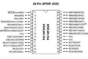
My microcontrollers of choice are PIC18 family 28 and 40 pin PICs which I have designed this unit to be pin-compatible for. Your unit can be designed for Arduino Atmel chips or any MCU you wish to use.
This Instructable is mostly intended to inspire ideas and some circuit pieces to help you develop a MDM for your own favorite family of MCU.
Also Please note the schematic and board layout are regarding Revision 0.3, it is far more advanced and has numerous corrections/features added to it, compared to Rev 0.1, which is photographed.
Step 1: Schematic Design
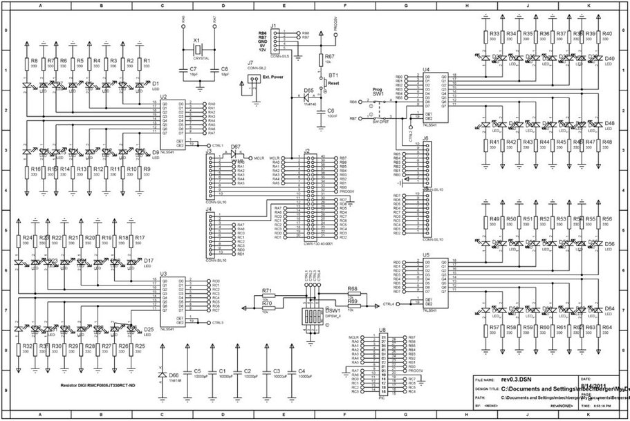
The schematic is large but fairly simple and can be broken down into some smaller parts.
- J2 is the 40-pin PIC socket, which connects pin-for-pin to the 40-pin IDE connector
- J8 is the 28-pin PIC socket, which will rest in between the 40-pin socket
- J3-J6 are arranged to form a 20×2 IDE cable connection for connecting the MDM to the PIC substitute board
- J7 is a header for running the MDM in a stand-alone configuration without power from the breadboard circuit
Each port has a 74LS541 connected to it which buffers and supplies current for 16 LEDs. A red LED has its cathode connected to the output pin and its anode ultimately connected to a +5V rail, and a green LED has its anode connected to the same output pin with its cathode connected to ground. The result is that when the PIC pin goes high, the corresponding 74LS541 pin does the same. When the pin is high the red LED has +5V on both sides of it, and thus will not light, but the green LED has +5V of potential on it now, and will light. When the pin is low then the red LED now has +5V of potential across it, and the green LED has GND on both sides of it and will not light. If the pin is rapidly switching from high to low, it will appear as if both LEDs are illuminated. Both LEDs would appear lit only in the event that the MCU pin is rapidly changing states, or if the 74LM541 has been disabled.
DSW1 is a DIP switch bank that allows the user to disable or enable the LED output ports if they so wish to. It will reduce the brightness of the port LEDs if you are not using that port for anything, or if the port is being used as an analog input port. When the pin is Tri-state then both LEDs will light up at 50% brightness. Due to limitations of the 74LS541, when the MCU pin is displaying tri-state, it will display as high. The only time that the output of the 74LS541 will go tri-state is when the enable/disable switch for that chip is enabled.
An oscillator is included on the board, and I recommend it be used because the crystal should be as close to the MCU as possible, and it is not a good idea for it to have to go through a ribbon cable to get there. It might also cause unwanted noise in the rest of the circuit and could affect ADC readings.
an ICSP header is included on the board, and can be enabled/disabled from the MCU pins with SW1.
Please press the “i” symbol at the top corner of each image to view it in full, readable resolution. Thank you.
Step 2: Parts List
Additional Parts information is available in the attached .xls file.Parts List:
- MDM PCB – 1 Piece
- MCU Substitution PCB – 1 Piece
- 74LS541 Tri-state buffer/line driver – 4 Pieces
- 5988170107F 0805 SMT LED GREEN 2V 20mA – 32 Pieces
- 5988110107F 0805 SMT LED RED 2.1V 20mA – 32 Pieces
- MC0805S8F330JT5E 0805 330 ohm SMT resistor- 64 Pieces
- CRG0402J10K/10 0805 10k ohm SMT resistor – 6 Pieces
- 08051C103KAT2A 0805 10nF SMT capacitor – 5 Pieces
- MC0805B104M160CT 0805 100nF SMT capacitor – 1 Piece
- MCDS04 4 position SPST DIP – 1 Piece
- 1N4148-TAP 1N4148 diode – 1 Piece
- 1n4148W 1B4148 diode SOD-123 – 2 Pieces
- MC9A12-4034 20×2 IDE connector – 2 Pieces
- MCLSS22 DPDT slide switch – 1 Piece
- M22-2512005 5 Pin header (row of 20) – 1 Piece
- MJTP1230 Reset pushbutton – 1 Piece
- 4840-6004-CP 40 Pin IC socket 0.6″ – 1 Piece
- 1-390261-9 28 pin IC socket 0.3″ – 1 Piece
- BG095-03-A-N-D Socket for crystal – 1 Piece
- MC0805N180J500CT 18pF Capacitor for crystal – 2 Pieces
- SPC19951 40 PIN IDE Cable – 1 Piece
- MC34739 20 Pin header for Sub PCB – 2 Pieces
 PIC_DEBUG_MODULE-BOM_rev_0.3.xls
Step 3: PCB Layout
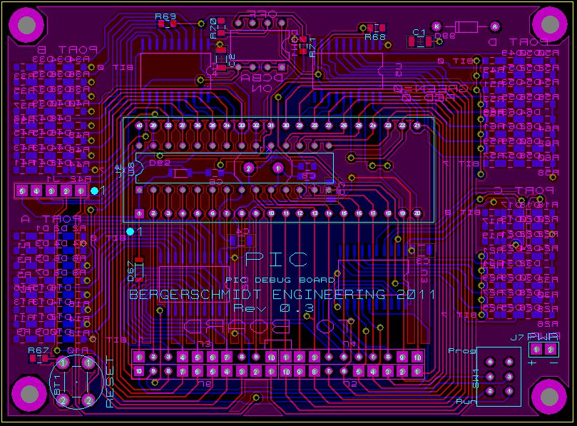
I wanted to make my unit as small as possible so I squeezed it as much as I could, using SMT components, into a board that is about 3.5″ by 2.5″. It would be difficult, but not impossible, to make it smaller still. I am happy with the size however.
I used the Proteus software package to develop my drawings and layouts. Eagle or another software package will work just as well.
If you want to develop your MDM using through-hole components you might have a difficult time making it a manageable size, and might have some further difficulty if you want to use a single-side PCB. I have my PCBs done by a company called Seeed Studio for relatively cheap, since this kind of production is virtually impossible to do at home.
This board would make a great SMT soldering practice project. The 0805 package size isn’t bad once you read some various techniques on the internet and test them out, and pick the one that works for you. Also a good hot iron with an appropriately small tip is important, and liquid flux makes life easier too.
Step 4: Completed Unit in Action
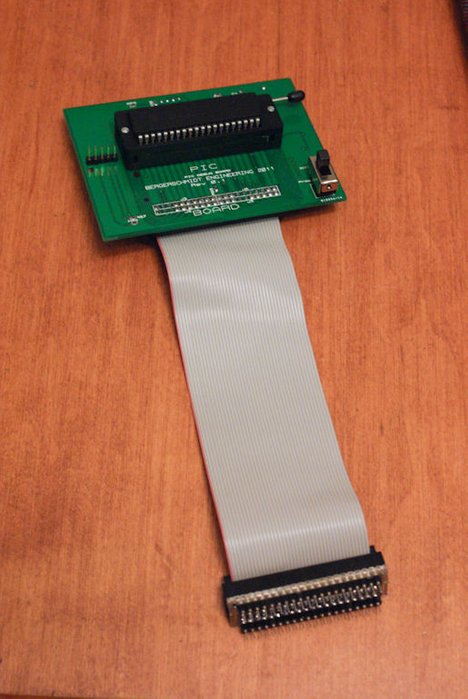
Once assembled the unit is ready to go. It can be used as a stand-alone device to test code, or inserted into a breadboard or PCB using the MCU substitution board. It gives an unparalleled visual connection to the circuit to allow you to develop code and debug issues at lightning speeds.
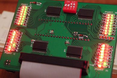
The image of the MDM operating below is running a test program on the PIC which puts each pin of each port high one by one. Port D and port P in the picture are disabled by the DIP switches, you can see that both LEDs are on and are dimmer than the LEDs on ports A and C below.
A great idea would be to develop a standard Arduino with this kind of circuit integrated right on the board!
I am always open to suggestions about how to make this better, or what other features it could benefit from. Pleas feel free to send me a message or post a comment. Thanks very much for reading.
Source : LED Microcontroller Debug Module
- What is the Microcontroller Debug Module (MDM)?
The MDM is a device that transplants the MCU to a separate module and connects by a 40-pin ribbon to a substitution PCB, providing buffered LED indicators per MCU pin for debugging. - How does the MDM indicate pin states without affecting the MCU?
Each port uses 74LS541 line drivers that source/sink current for LEDs so the MCU pin and breadboard circuit are not affected. - Can the MDM be used without powering from the breadboard circuit?
Yes, a header (J7) allows running the MDM in a stand-alone configuration without power from the breadboard circuit. - Why is an oscillator included on the MDM board?
The oscillator is included so the crystal stays close to the MCU, avoiding ribbon-cable routing that could cause noise and affect ADC readings. - What happens when an MCU pin is tri-stated on the MDM?
Due to 74LS541 limitations, a tri-state MCU pin will display as high, and when the 74LS541 is disabled pins will appear dim with both LEDs lit at about 50%. - How can LEDs for a port be disabled or dimmed?
A DIP switch bank (DSW1) allows enabling or disabling LED output ports, reducing brightness or turning them off. - Which MCU families is this MDM designed for?
The author designed it to be pin-compatible with PIC18 family 28 and 40 pin PICs, but it can be adapted for Arduino Atmel or other MCUs. - Does the MDM require circuit modifications to use?
No circuit modifications are required; the module transposes each pin directly and plugs in remotely via a ribbon cable and substitution PCB. - What software was used for PCB layout and how big is the board?
The author used Proteus for layouts; the SMT board is about 3.5 by 2.5 inches.