This project describes the first part of the following two projects:
- A wireless doorbell transmitter as described in this Instructable
- A wireless doorbell receiver to be described in the Wireless Doorbell Receiver Instructable
When I am sitting in the backyard of my house I cannot hear it when somebody is ringing the doorbell at the front door. This problem can, of course, be solved by purchasing a wireless doorbell but it is more fun to build it yourself. Next to that I sometimes here of interference problems with other wireless doorbells so the more reason to make one of your own.

When the doorbell switch is pressed this circuit sends a message via a simple 433 MHz RF transmitter to a wireless doorbell receiver while keeping the original doorbell functionality intact. The circuit is placed in series with the original doorbell switch and emulates the doorbell switch for the original door bell. This adds the possibility to prevent that the doorbell keeps on ringing when someone is continuously pressing the doorbell switch.
The circuit also contains a switch that makes it possible to disable the transmission of a message to the wireless doorbell while keeping the original doorbell operational. The circuit is powered by the 8 Volt AC doorbell transformer which also powers the original doorbell.
As always I built this project around my favorite micro controller the PIC but you can also use an Arduino. Arduino fans may recognize the transmission protocol that I describe later since I used a ported version of the Arduino Virtual Wire library for a reliable transmission of the RF message.
Step 1: Required Components

You need to have the following components for this project:
- A piece of breadboard
- PIC microcontroller 12F617, see win-source
- Fuse holder + fuse 100mA Slow
- Rectifier bridge, e.g. DF02M, see win-source
- Electrolytic capacitor 220 uF/35V and 10 uF/16V
- 3 * ceramic capacitor of 100nF
- Voltage regulator 78L05, see win-source
- 433 MHz ASK RF Transmitter
- Resistors: 1 * 10k, 1 * 4k7, 3 * 220 Ohm
- An NPN transistor, e.g. BC548 see win-source
- Switch
- LEDs: 1 Red, 1 Green
- A plastic housing
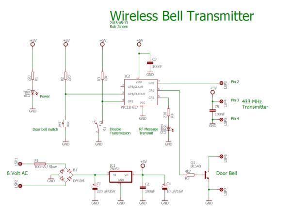
See the schematic diagram on how to connect the components.
Step 2: Designing and Building the Electronics

All control is performed by the PIC12F617 in software. Before designing the circuit I needed to check how I could easily activate the original doorbell. The model I have is a Byron 761 which generates a ding-dong sound and can be powered by a 9 Volt battery or via an 8 Volt AC transformer. After some measurements on the original doorbell I found out that the connector for the doorbell switch had one pin to ground and one input pin floating at 3.5 Volt. When closing this connection – so pressing the doorbell switch – only a current of 35 uA flows through it. Because of this I decided to use a transistor with open collector and the emitter go ground to activate the original doorbell which worked fine.
Since the doorbell switch is outside I did not like the fact that only a very small current flows through the doorbell switch when it is pressed since it may ring the bell while nobody is there when it becomes humid (not sure if this happens in reality). In the circuit I used a 220 Ohm pull-up resistor so when the doorbell is pressed, a current of 23 mA goes through the doorbell switch.
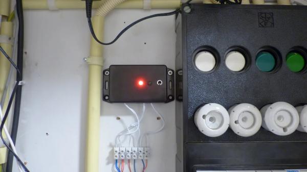
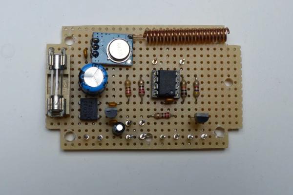
The rest of the design is straightforward with a standard rectifier bridge and voltage regulator to create a stable 5 Volt power for the circuit. Building the circuit can easily be done on a small breadboard. In the pictures you can see the circuit as I built it on the breadboard including the final result when put in a plastic housing.
Step 3: The Software
As already mentioned, the software is written for a PIC12F617. It is written in JAL. In the past I have been using RF transmission using a 433 MHz RF module but I used my own simple transmission protocol, as you can find in this Instructables: RF-Thermostat
My protocol works fine as long as the distance is not too big. For this project I needed a more reliable RF transmission protocol. After some research I found the Virtual Wire library which was written in C for the Arduino. Since I use a PIC with the JAL programming language, I ported this library from C to JAL and used it in this Instructables. This Virtual Library has a much better reliability than the simple protocol I used. Of course transmission can always go wrong. In order to minimize the loss of a transmission each message is sent out 3 times using a different sequence number for each new message.
In this project the PIC runs on an internal clock frequency of 8 MHz, where Timer 2 is used by the Virtual Library to send the RF messages with a bit rate of 1000 bits/s.
When the outside doorbell switch is pressed, the software does the following:
- Debounce the doorbell switch. If it is still pressed after a debounce time of 50 ms, the program continues with the next step, otherwise it will ignore the doorbell switch being pressed.
- If the Disable Transmission switch is not active, a 3 byte message – address, command and sequence number – is sent via the 433 MHz RF transmitter and the green LED will turn on for one second. In parallel the original door bell will be ringing by activating the BC548 transistor for half a second.
- If the Disable Transmission switch is active then the same actions are performed except for the RF transmission which will not happen. In this way the wireless doorbell can be switched off remotely while keeping the original doorbell operational.
- Only when the doorbell switch is released again after being pressed, a new transmission and new ringing of the doorbell will be initiated. This prevents that the doorbell keeps on ringing when the doorbell switch is continuously pressed.
The JAL source file and the Intel Hex file are attached. If you are interested in using the PIC microcontroller with JAL – a Pascal like programming language – please visit the JAL download site.
Have fun building your own project and looking forward to your reactions.
Source: Wireless Doorbell Transmitter
