Summary of Arduino Wireless Animatronic Hand
This article details the construction of a wireless animatronic hand controlled by a custom glove, operating independently without a computer. The project involves building a control glove with flex sensors and an Arduino, paired with a robotic hand driven by servos. The creator uses 3D modeling software (EAGLE CAD) for PCBs, tests accuracy against human hand movements using high-speed video analysis, and reports angular differences between the user's hand and the robot's response.
Parts used in Wireless Animatronic Hand:
- Arduino w/ ATMEGA 328
- Xbee w/ Shield
- 5 Flex sensors
- Glove
- 9v battery
- Hook up wire
- Custom PCB making tools
- 5 resistors (10k)
- Electrical wire tubes
- Fishing tackle
- Electrical tape
- LEGOS
- 5 servos
- Exacto knife
- Elastic material
- Double sided tape
BTW!!!!! This instructable is awsomeeeeeeThis is a very simple but at the same time a very hard project depending on your skill level. Lets get to building!
Step 2: Control Glove
Materials:
Arduino w/ ATMEGA 328
Xbee w/ Shield
5 Flex sensors
Glove
9v
Hook up wire
Custom PCB making tools
(5) 10k resistors
1. Power both of the Arduinos to make sure they operate correctly.
2. Assemble the Xbee radio shields.
3. Connect the Xbee shields to the Arduino by placing on top of the Arduino.
4. Connect the Xbee’s to the shields and connect them via USB.
5. Take the ATMEGA328 chip off the Arduino so there is a direct link between the computer and the Xbee radio.
6. Configure them in XCTU (default settings will work).
7. From here i built my own PCB (I’m not going to touch on how to do that, there are other very good tutorial out there) I used the data sheet for the sensors from this site, this is also where i got these sensors:
http://www.sparkfun.com/products/8606
8.From here i put all the boards together and tested it out to see if everything worked (powered on).
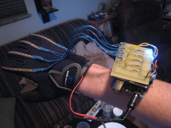
9. I sewed the flex sensors onto the glove by poking a hole at top and running the string over and under the sensor so it can still freely move.
10. i built the arm band with some elastically and some STRONG double sided tape.
Step 3: Custom PCB (Glove)
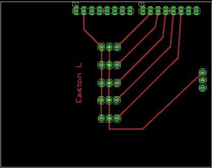
So for the glove i made a custom PCB to connect to the arduino. This PCB is for the 5 flex sensors for arduino inputs. This is my first PCB so it wasn’t by any means complex nor professional. I made this in EAGLE CAD and used the Sharpie Method.
Step 4: The Hand!
Materials:
electrical wire tubes (http://www.instructables.com/id/Simple-Animatronics-robotic-hand/)
fishing tackle
electrical tape
LEGOS
5 servos
xbee w/ shield
arduino ATMEGA 328
exact o knife
This took the longest to build…
1. I researched hands and found a diagram where the joints are.
2. I then cut the joints with the exacto knife
3. I put all the fingers together without the thumb.
4. i put the four fingers together and reinforced them with legos
5. i taped the securely and put the thumb over those so it would have human like flex.
6. i taped the servos together filling the spaces with Styrofoam
7. i added all 5 servos to the hand with legos and tape
8. I built the circuit on a breadboard with just delivering power the servos and having the control wires into the Digital input on the arduino
9. i ran fishing tackle from the finger tip through the tube and anchored it onto the servo
Step 5: Hand PCB Shield
For the hand i am still in the process in building a pcb to take away the wires and reduce space. This time i am using to toner transfer method. I again made the schematic and board layout in EAGLE CAD. i used magazine paper to print onto. I engineered this to be used as a shield on the arduino.
Step 6: CODE!!!
The Very first thing you want to do is make sure your shield or xbee’s are unplugged from the arduino. Or make sure the correct jumpers are the in the right place (in my case). I have written this code and if you do use it want credit.
This is the code for the sending Arduino:
Step 7: How I Tested This
Here is some of my work for it:
So pretty much what i did was take a HD video at 60 fps to get high resolution skills.i came up with three positions to test, fully extended, half extended and unextended. From here i went into geometers sketchpad and found the angle of each finger at each position for both hands. From here i was able to compare a real hand to my animatronic hand.
Step 8: Results
Upon conductions of the experiment, using the variables finger, angle, sensor value and position, the fallowing results were produced. During the first test I measured the angle relationship between my finger and the corresponding finger on the animatronic hand. I found that the index finger, middle finger, ring finger, and pinky all had about the same sensor value from the flex sensors. The thumb on the other hand was limited in movement compared to the other fingers, and therefore the sensor data was in a smaller range. I then came up with three positions to test, fully extended, half extended, and unextended. From here I created a video of all my fingers at these different positions. I then analyzed the videos through the use of editing software and found the angle of each finger at each position.
I then conducted the same procedure for the animatronic hand, finding the angle of each finger at each position in the process. I found that at the fully extended position the relationship between my finger and the corresponding finger on the animatronic hand was about a 20° difference. At half extended the relationship was the closest at about a 10° difference. At unextended I noticed the most difference with my fingers bending almost 30° more than the animatronic hand. The thumb was the most consistent finger with only about 10° difference on all three tests. Overall, the comparison of my hand compared to the animatronic hand was greater than I thought. The position with the greatest difference was fully flexed. What all this means is that the animatronic hand has a relationship with my hand.
fishing tackle
electrical tape
LEGOS
5 servos
For mora detail: Arduino Wireless Animatronic Hand
- Does the project require a computer to operate?
No, the wireless animatronic hand does not need a computer to operate once built. - How are the flex sensors attached to the glove?
The sensors are sewn onto the glove by poking a hole at the top and running string over and under the sensor. - What software was used to design the PCBs?
EAGLE CAD was used to make the schematic and board layout for both the glove and hand PCBs. - How is the arm band constructed?
The arm band is built using elastic and strong double sided tape. - What method was used to test the hand's accuracy?
The creator used HD video at 60 fps to measure finger angles and compared them to the animatronic hand. - Which finger had the most consistent movement?
The thumb was the most consistent finger with only about a 10° difference on all three tests. - At which position was the angle difference greatest?
The position with the greatest difference was fully flexed, where fingers bent almost 30° more than the animatronic hand. - What components reinforce the fingers of the hand?
Legos were used to reinforce the four fingers together. - Can I use this code without giving credit?
The author requests credit if you use the written code provided in the article.