
Summary of what is proteus example circuits librarproteus software
This tutorial shows how to use Proteus (ISIS and ARES) to create and simulate a simple DC power-supply circuit with a switch and DC voltmeter, covering project setup, selecting components from the library, and brief descriptions of each component used.
Parts used in the Circuit with a switch and DC Voltmeter:
- Battery
- LED
- Resistor
- Switch
- Wires
- DC Voltmeter
In this tutorial, we have to learn about how to Circuit with a switch using DC Voltmeter using Proteus.
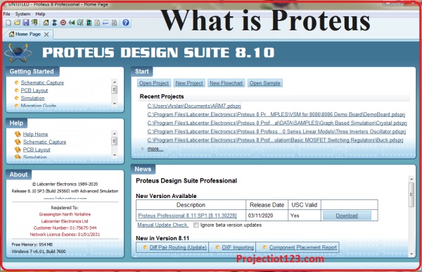
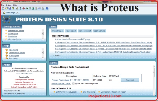
Proteus and Simulation Software – Introduction
What is Proteus?
Proteus is a simulation and design software use for lab centre Electronic for Electrical and Electronic design circuits.. Proteus is the best simulation software for various with microcontroller. It is mainly common software because of availability of almost all microcontrollers in it. So it is a handy tool test programs and embedded designs for electronic hobbyist. You can see your programming in Proteus Software.
After simulating your circuit in Proteus you can easily make PCB design with it. In short you can say that it could be all in one package. So now I can say that you have a little bit idea about Software.
It is a software containing Schematic, Simulation and PCB designing.
- ISIS:
ISIS abbreviation is Intelligent Schematic Input System. ISIS is used to draw schematic and simulate the circuit in real time. The Simulation allows human access during run time, providing real time simulation.
- ARES:
ARES Stands for Advance Routing and Editing Software. ARES is used for PCB designing. It has the feature of viewing 3D view of the designed PCB along with components. The designer can also develop 2D drawings in it
First of all you will have to download the Proteus software.
- After install the software
- Open Proteus and check whether the Arduino libraries are installed or not.
- In Proteus, create a new project
Where you want to save your project.
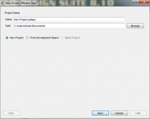
- Name the project according to your need
- Then click on next button
- The next step is to select the Create Schematic option and
- Then click on next button
- The next step is to select the Create a PCB option and
- Then click on next button
- Then click on next button
- Then click on next button
- Then click on next button
- The next step is to select the No Firmware Project option and
- Then click on next button
- After finishing the settings, you can see the empty workspace. Here, you can place your required components from the library.
- Click on the P, you will see a list of components. Here, you can find all types of components for simulation.
Now We Will Start Our Project
For making simple power supply circuit we have to use this following components.
- Battery
- LED
- Resistor
- Switch
- Wires
- DC Voltmeter
First we have to select the components from the library
Battery:
It is like a container consisting of one or more cells, in which chemical energy converted into electricity. We can say that it is used as a source of power.
- Now Second component is LED
LED is an abbreviation used for Light Emitting Diode. It is a basically a pn junction diode that has the ability to give off light when certain voltage is applied to it.
- Now Third component is Resistor
A resistor is a flow of electric current. Something that could tame the flow in a controlled way that device is called a resistor.
- Now Fourth component is Switch
Switch are an important part of most electronic circuits. In the simplest case, most circuit contain an on/off switch. In additional to the on/off switch, many circuit s contain switches that control how the circuit works or activate different features of the circuits.
- Now Fifth component is Wires
A wire is a long thin piece of metal that is used to carry electric current. If you rap something with wire such as a piece of equipment, you put wires inside it so that electricity or signals can pass through it.
- Now Sixth component is DC Voltmeter
Voltmeter is used for measuring voltage or the potential difference. If we place a high resistor in series with the Permanent Magnetic Moving Coil galvanometer, then the entire combination acts as DC Voltmeter. This resistor is also called Multiplier.
After selecting all the components from library now its time to simulate our project.
In this article, I showed you how to use Proteus for simulation your project. You installed the Proteus and performed the project: Circuit with a switch and DC Voltmeter.
Source: what is proteus example circuits proteus software
- What is Proteus used for?
Proteus is used for schematic design, real-time simulation (ISIS), and PCB design (ARES) for electrical and electronic circuits. - How do you start a new project in Proteus?
Open Proteus, create a new project, choose where to save it, name it, and follow the wizard to create schematic and PCB files. - How do you check for Arduino libraries in Proteus?
After installing Proteus, open the software and check the library list to see whether Arduino libraries are installed. - Which Proteus module is used to draw schematics and simulate circuits?
ISIS (Intelligent Schematic Input System) is used to draw schematics and simulate circuits in real time. - Which Proteus module is used for PCB design?
ARES (Advanced Routing and Editing Software) is used for PCB designing and offers 3D PCB view and 2D drawings. - What components are required for the example power supply circuit?
The tutorial uses a battery, LED, resistor, switch, wires, and a DC voltmeter. - How is a DC voltmeter modeled in the tutorial?
The DC voltmeter is modeled as a permanent magnet moving coil galvanometer with a high series resistor (multiplier) to measure voltage. - What is the role of a resistor in the circuit?
The resistor controls or limits the flow of electric current in a controlled way.
